This new version of Woodwork for Inventor v8 (available for Inventor 2015, 2016, 2017 & 2018) is an exciting release and well worth the wait. So let’s start with what I can honestly say will revolutionise the way you think about creating and using a template carcass in your assemblies.
Forget your parameter linking, icopy, adaptive shenanigans! It’s time to use the new Woodwork for Inventor iBOX tool! it sounds small, but believe me it packs a punch, when you hear what it can do. In fact, It’s already got me thinking how easy we could utilise Revit model layouts. More about that later.
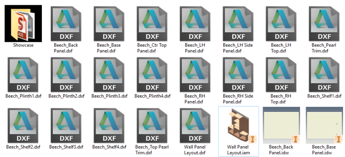
Another area that has seen some long awaited attention is to be able to generate a nest of panels in the CAM version. Nice job guys, this certainly keeps everything tight and integrated in the package. So let’s dive in….
Summary of What’s new
Dress Up Function NEW – Panel Mitre
Materials NEW – Replace material tool for model & BOM replace in specification
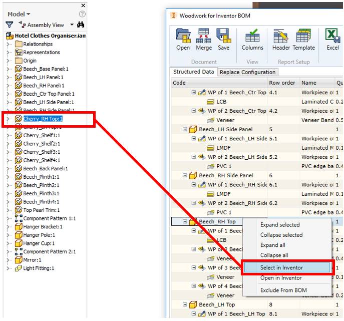
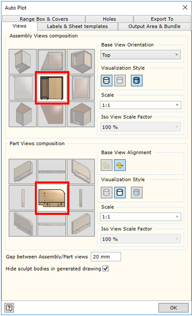
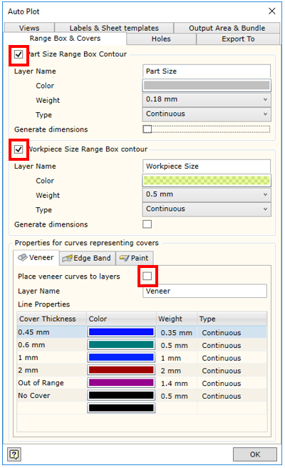
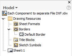
Drawings NEW – Can use DWG in AutoPlot, Hole Tables enhanced, Automatic visualisation of hole parameters in a drawing and changing the hole table form.
Visualisation of the information created by the Woodwork for Inventor add-on in the drawings created by the user.
Parts NEW – 3D hole annotation
Assembly NEW – iBox & enhanced Attach command
CAM NEW – Preliminary Nesting & Improved automatic clamping detection
Panel Mitre
An extension to the Skeleton Dress up capability, we can now mitre panels together in addition to the normal trim. All ready for further jointing methods such as adding biscuits.

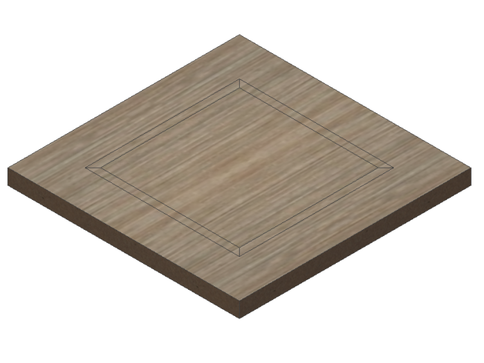
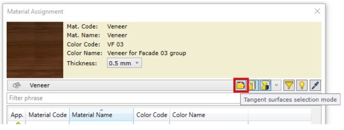
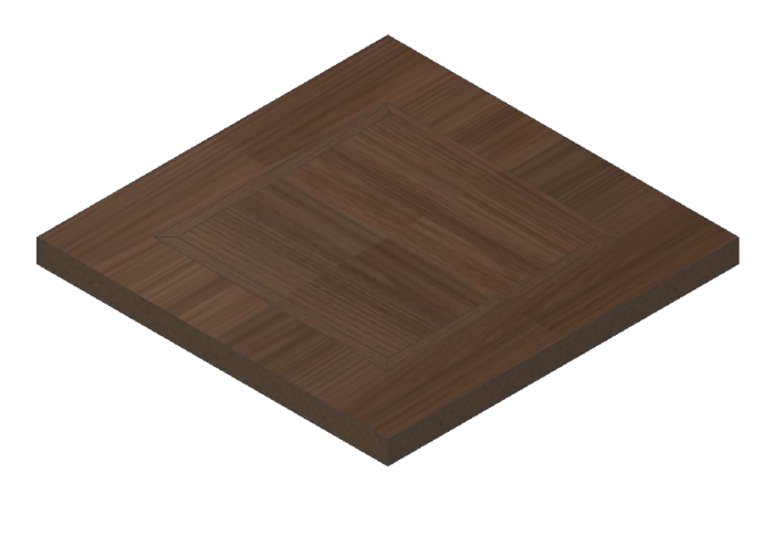
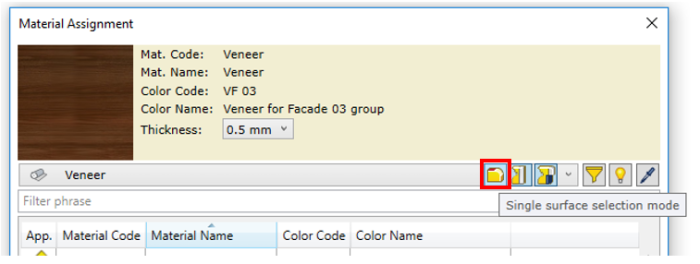
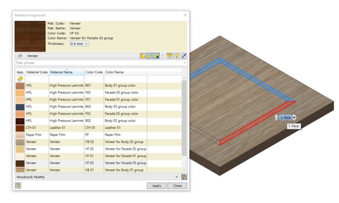
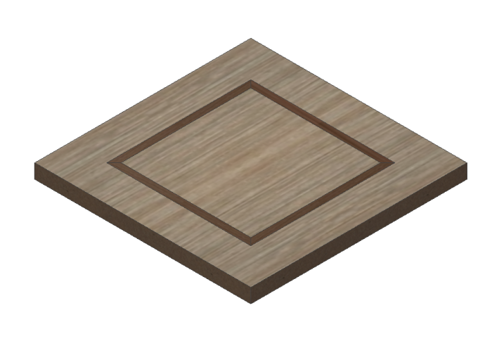
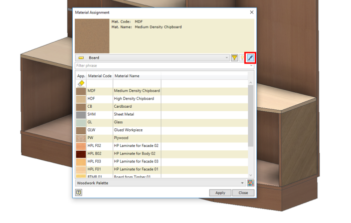
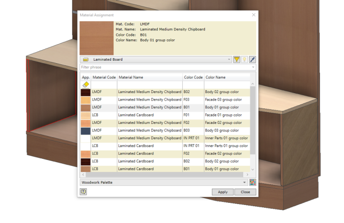
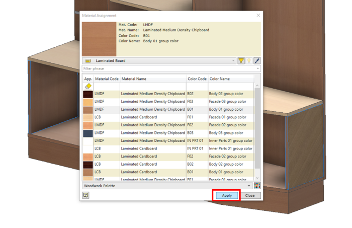
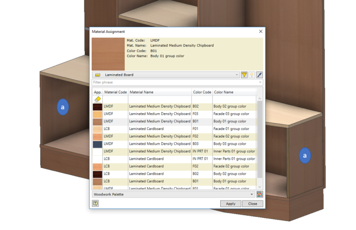
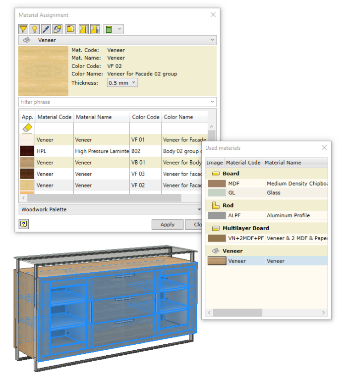
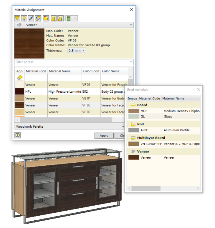
Replace material tool in the model
Simply change all used materials in the model with a different material within the apply material dialogue box. This great addition makes swapping out materials a whole lot easier.
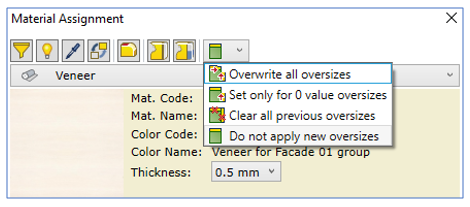
Pre-set material over-size
While creating a material, the user now has the option to pre-set the workpiece over-sizing. With this feature you do not need to assign an over-size as a separate command afterwards because it is applied when the material is assigned.
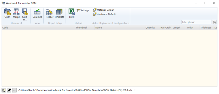
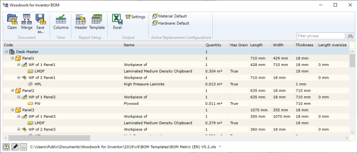
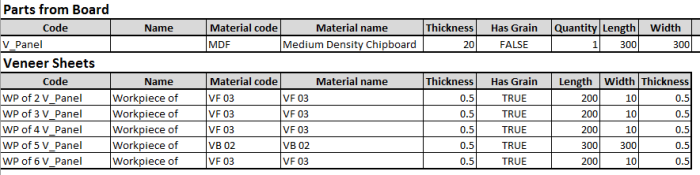
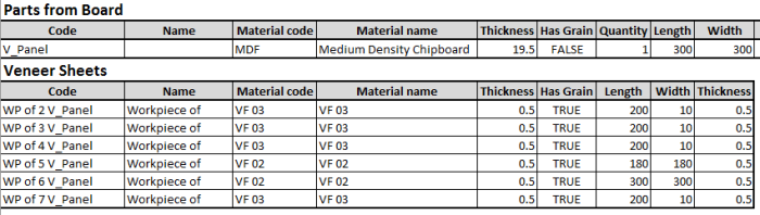
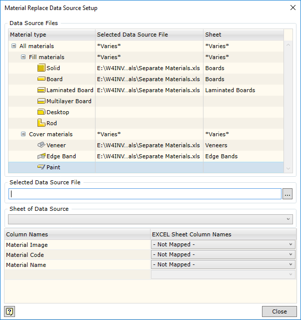
Improved material and colour replacement in the BOM specification
The user can now link each type of material to Excel tables. This improves the application and provision of data replaced in MS Excel tables for each material type and facilitates navigation in MS Excel table entries.
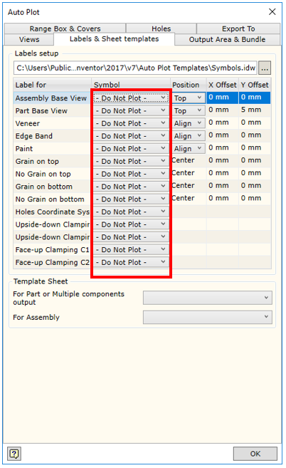
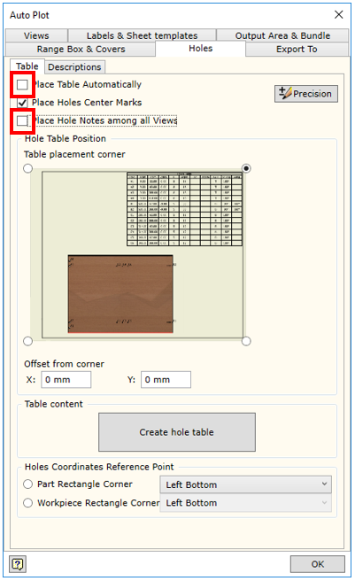
Automatic visualisation of hole parameters in a drawing
The automatic plotting of drawings now allows the users to request automatic export of hole position parameters into the part drawing.
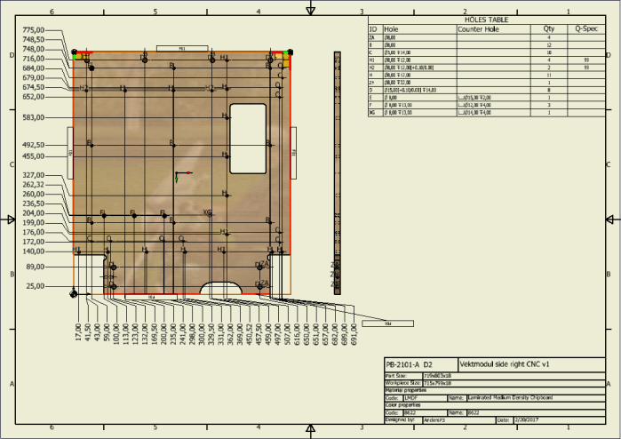
Changing the hole table form
The user can create his own hole table templates in the Woodwork for Inventor drawing template based on which of these tables will be generated in the drawing. This ensures that the form of the hole table being generated are better suited to the user’s needs.
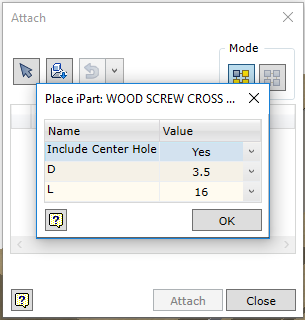
Attach tool enhancement
When attaching iPart configured hardware using the attach tool, you will now be prompted to enter the ipart configuration on placement.
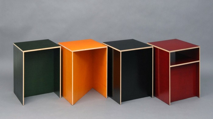
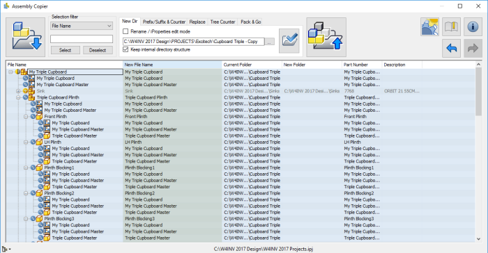
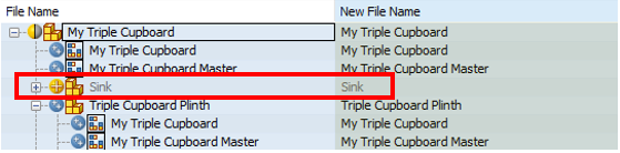
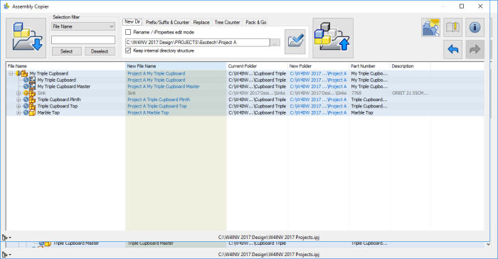
iBOX Components
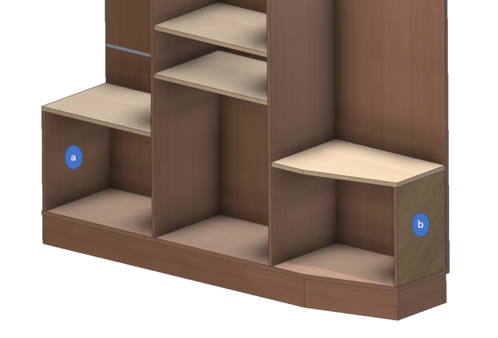
You can now author iBOX assemblies to use in concept layouts. Either create your own inside Inventor or you can leverage the solids created from other 3D packages such as Autodesk Revit.
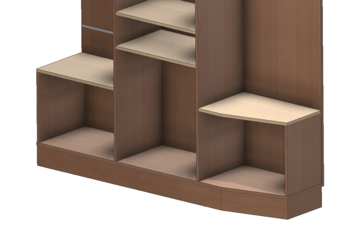
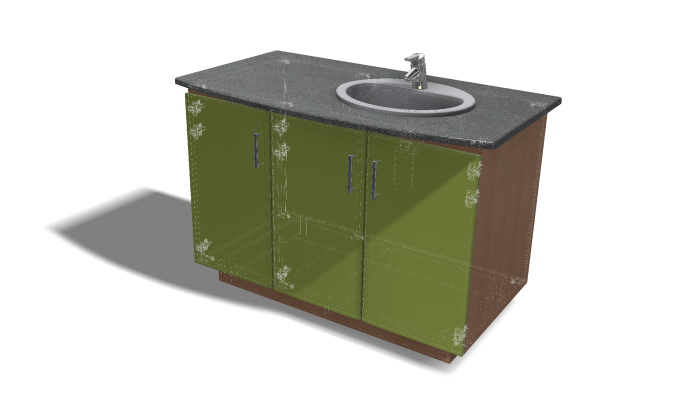
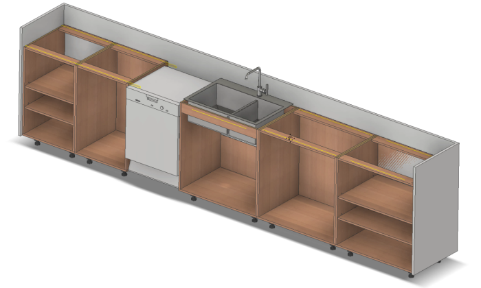
This example could be a parametric concept layout of a Tea Point or Kitchen. We can define simple volumes that outline where cupboards would go, drawer positions and door spaces.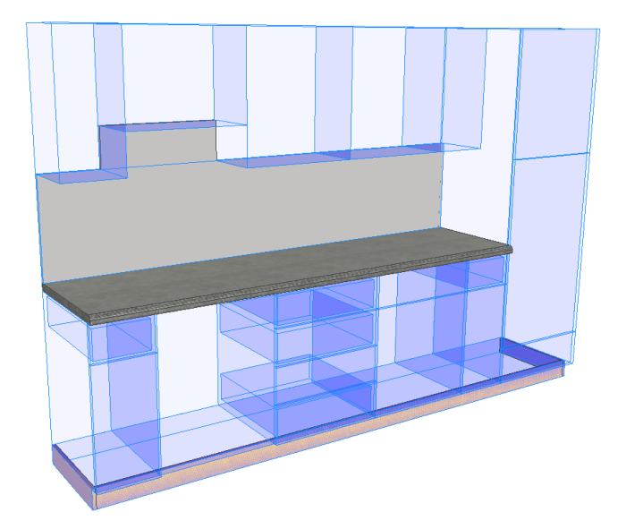
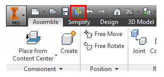
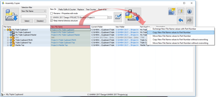
By using insert ibox tool  , you can quickly place your template cabinet and it will automatically size itself to the space indicated.
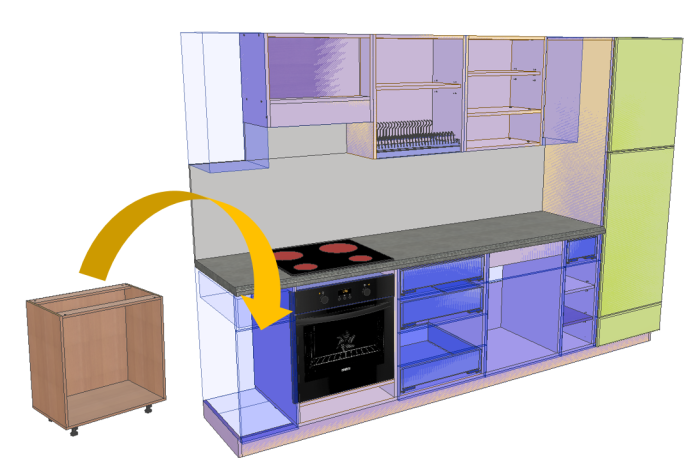
Follow the prompts and select the sold first then top, front and right faces.

Job done! It’s easy and each unit will be unique to amend further using the embedded iLogic.

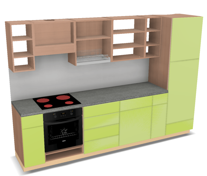
So this got me thinking, what if we imported a kitchen layout from Autodesk Revit? I used the standard Architecture model in this example. Quite simply yes you can, you get the bounding box of the unit as well as drawer fronts. I did some restructuring of parts in the Inventor browser to make some sub assemblies and general folders to group together parts.
Add your carcass (Woodwork for Inventor comes with a selection of ready built cabinet templates so used the sample iBox models here but you can create your own). However, these models had 100mm plinth details and the Revit model cabinets terminated at the finished floor level. I moved the bottom face of each Revit imported body using Inventor’s direct edit tool -100mm and after an iBox refresh  all cabinets updated. So it doesn’t matter where your layout comes from. If inventor can import it then you can save a lot of time taking your concept to manufacturing.
I’ll cover this workflow in more detail in a future blog post.
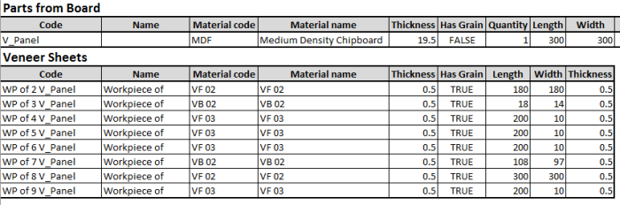
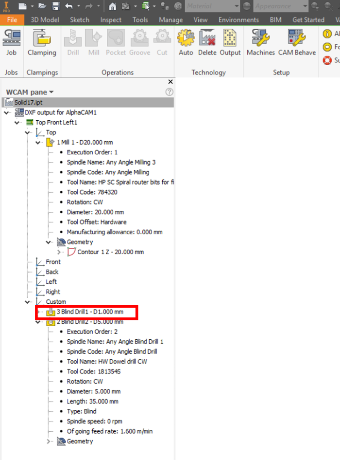
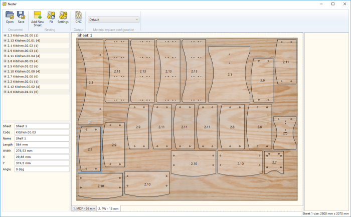
CAM – Nesting
You can create CNC technologies for all parts which are suitable for the CNC nesting router machine, and later combine them and create a common nesting program for cutting parts from a single sheet of material. In this environment, individual CNC part technologies can be moved, turned, transferred to a different sheet, etc.
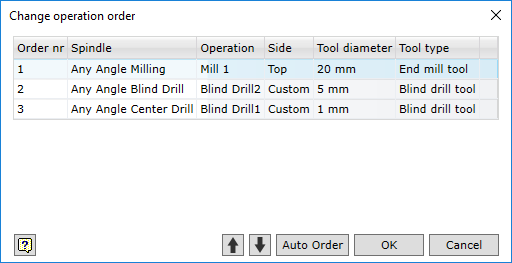
Improved automatic clamping detection
The clamping detection algorithm in the automatic CNC technologies has been improved. The user can now indicate more criteria that influence the automatic clamping option. For example, the user can set basic reference planes for all parts of the product, taking into account their orientation within the product. It is possible to set assessment weight for all the criteria, in this way adjusting their impact on the clamping selection. This adds more accuracy to the automatic creation of CNC programs performed by the Woodwork for Inventor add-on.