What’s New Woodwork for Inventor v11

What’s New Woodwork for Inventor v11

Woodwork for Inventor was released back in May this year and I haven’t really had time to review this release in earnest due to other priorities. A major Pandemic springs to mind and sometimes, life just gets in the way. Anyway… until now, so here goes.

ADAPTIVE SCULPT

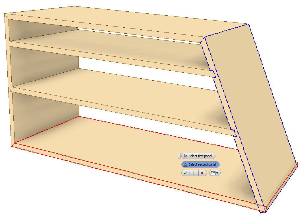
Before v11 the Sculpt tool has always been a useful tool to remove material or even add material to your parts at the assembly level. Up until now, we have had to manually re-sculpt our assemblies once a parametric change has occured otherwise the cutout would remain in the original position.

Now with v11, the sculpt tool can now work in unison with your parametric changes. How? Adaptivity is how. In W4I it’s been called “Associative”.

By enabling “associative” when creating your sculpt, it will automatically set all affected parts and sub assemblies to become “Inventor adaptive”. Should you wish to revert back & remove adaptivity then removing your sculpts will not clear the adaptivity flags set. You will need to manage these manually by right clicking the parts in the model browser and switch off. If the parts are buried in a sub assembly you will need to open the part and clear the adaptively used in assembly button under Tools> Document Settings. It’s worth taking some time to understand more about the pros & cons of using adaptivity.

Extract about Adaptivity from the Autodesk Inventor Online Help system <Click Link>

MULTILAYER BOARD MATERIAL

This interface is now overhauled to make it easier to create Multilayer Boards. You now have the choice to create a local material added to the part or a sharable material added to the W4I material database.

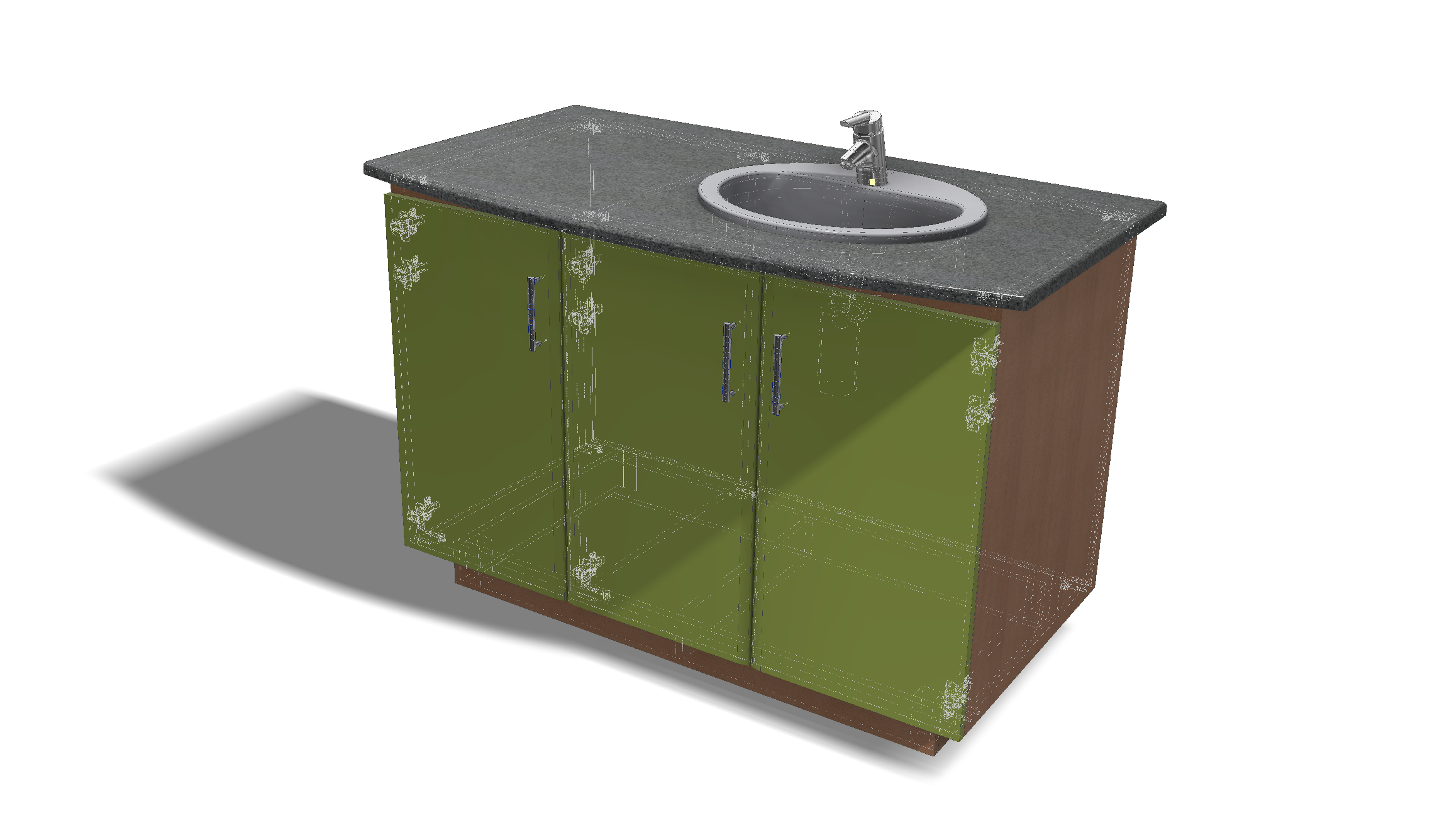
A typical scenario might be making up a composite worktop. 12mm Corian on the top with an 18mm sub-top made from MDF, however you need a bonding zone of 2mm for Adhesive.

The buildup will require you to have the W4I materials you want to assign already created in your own read/write library. You can then store the custom Multilayer material in the local part or share in your custom library. Two new icons have been provided to choose the Material Origin.

The output can be seen on the AutoPlot where the breakdown matches your described build up and of course the BOM Specification.

Breakdown of Multilayer Board automatically reported

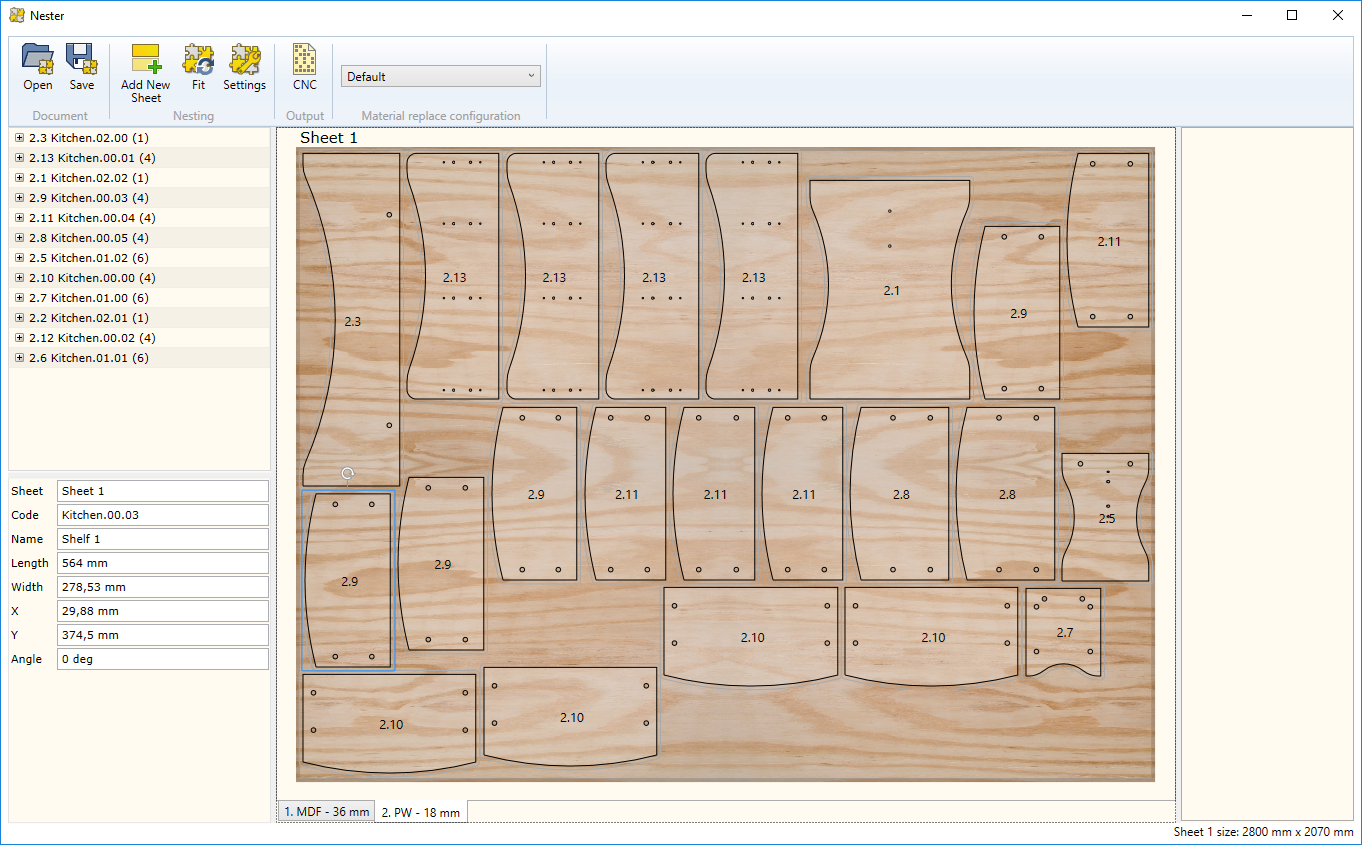
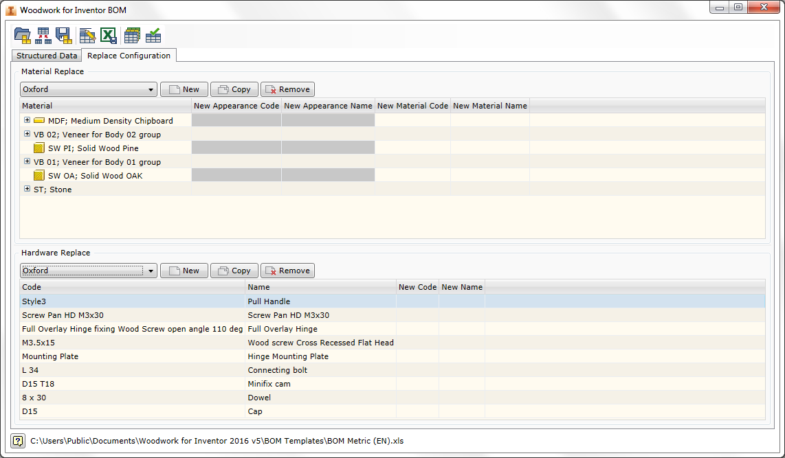
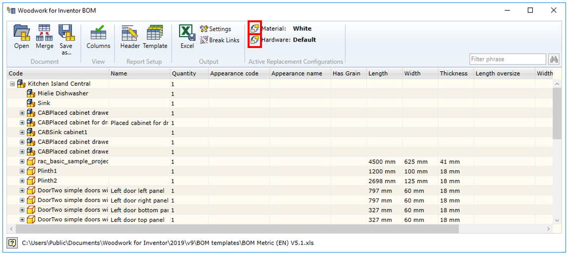
REPLACE MATERIAL (Configuration)

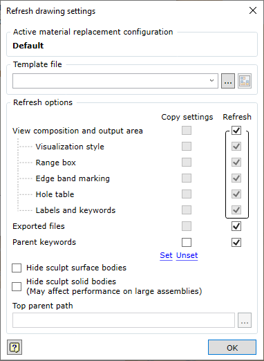
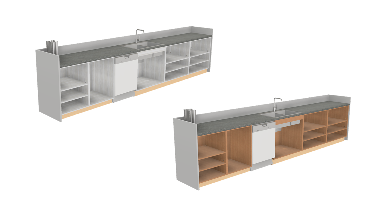
Material & hardware replacement tool interface has been updated to make it easier to understand what’s applied and to ensure you now have the option to lock the configurated material into the part. The intent behind this tool remains the same as it was when first introduced. You have a design as a default but wish to vary the applied materials via a customer request and potentially source alternative hardware. The dialogue box now only shows current materials which includes the modified materials.

To use the Replacement Materials & Hardware you will need to configure the spreadsheet that is linked to the model. Here we are creating a New Configuration but it could be called Customer A, Customer B or Light Oak, Dark Oak.

Let’s take a look at these five steps.

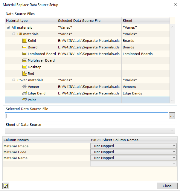
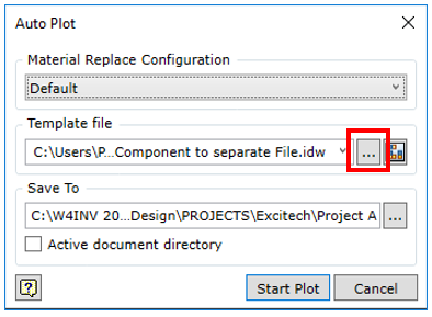
Step 1. Choose Setup

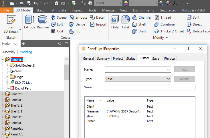
Step 2. Navigate to locate your custom lookup spreadsheet. There is a sample Replacement data by Material type.xls available in the C:\W4INV 2019 Design\Projects\Samples\Replacement Data\Materials folder. This will give you an idea of how to build your own Company spreadsheet.

Step 3. Once you have connected the spreadsheet for this configuration you can map the Column Names as below Step 4.

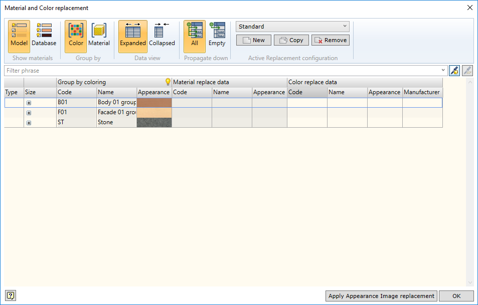
Now you should see the mapped data pulling through into the dialogue box.

Step 5. Double click the colour image you would like to use and it will set the material for you.

Customer A – Material Configuration set to Pastel Yellow
Customer B – Material Configuration set to Green Mamba

You can be selective in which components can be modified by de-selecting the ticked items on the left of the dialogue. The material will only effect those components that are active when using the “Apply Appearance Image Replacement” button.

Once the material has been written into the part you can now lock that material and unlock if required. Write, does just that where it will assign the material and Clear removes the material allowing you back to default and to start again.

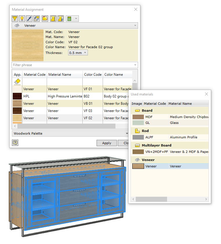
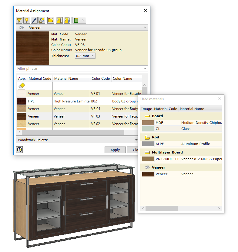
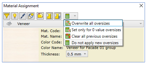
USED MATERIALS (Global change)

An undocumented new addition. You can now toggle the materials on/off/shaded/transparent with the addition of some new buttons in this release.

REFERENCE PARTS & ASSEMBLIES

Parts & assemblies that are flagged as reference in the Inventor BOM are now removed from the W4I BOM Specification whereas in v10 or earlier they did not. Why is this important? Using Reference flags on parts etc is normal workflow for Inventor users.

Take the example where you place a component such as a Glass clamp. The issue is, the part knows it comes as a set of 4 in a box when ordered but if you were to place them individually you would end up ordering 16.

Therefore, you need to place all 4 in the assembly to show pictorially and make 3 of them Reference.

When you run the W4I Bom Specification you will see a warning reminding you that there are reference components in your assembly.

The BOM Specification now reports correctly.
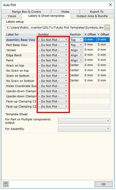
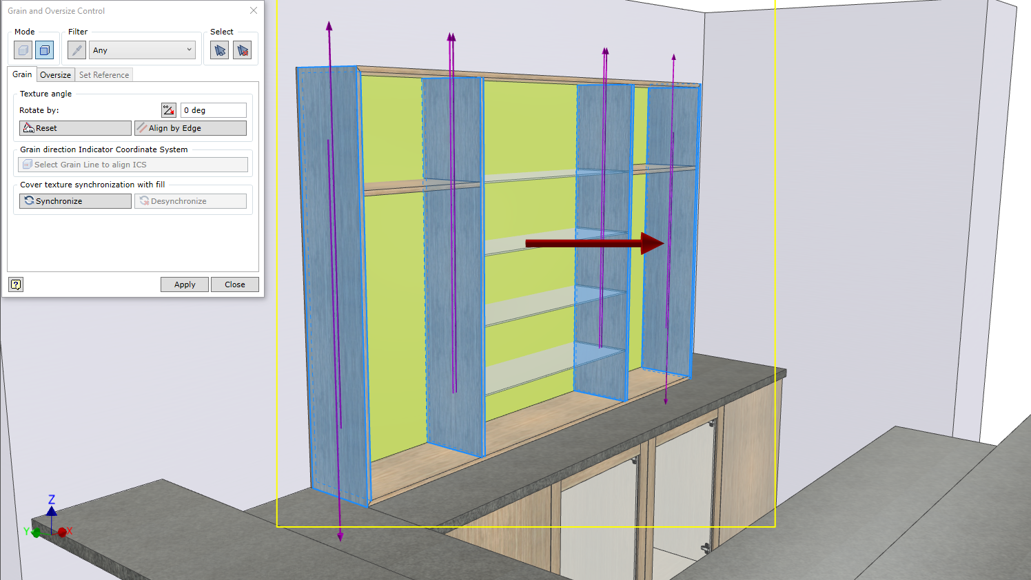
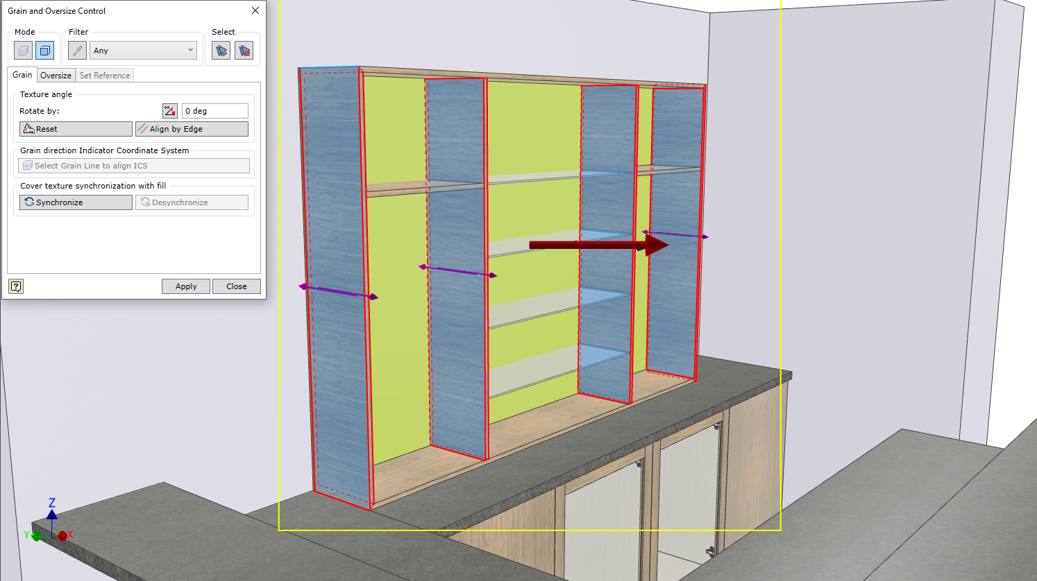
EDGE BAND LEGENDS

You can build your content for the cover legend

NameInserts a keyword that exports cover material name into the template.  
CodeInserts a keyword that exports cover material code into the template.  
Color NameInserts a keyword that exports cover material colour name into the template.  
Color CodeInserts a keyword that exports cover material colour code into the template.  
ThicknessInserts a keyword that exports cover thickness into the template.  
WidthInserts a keyword that exports cover width into the template.
SeparatorDefines a separator that is used when descriptions of several types of edge bands have to be exported on the same side.  
Coinsident to range box edgeDefines export of edges that coincide with the Surrounding Box. Export of this type of covers cannot be disabled.  
Tangent to range box edgeDefines export of tangent edges that coincide with the Surrounding Box.  
Point touch range box edgeDefines export of point edges that coincide with the Surrounding Box.  
Indirect touch range box edgeDefines export of indirect edges that coincide with the Surrounding Box.  
Prefix/SufixAllows specifying a prefix or suffix for the exported information about each type of cover.
Top Legend{Item.CoverWorkpiece.Top.Legend}
Bottom Legend{Item.CoverWorkpiece.Bottom.Legend}
Left Legend{Item.CoverWorkpiece.Left.Legend}
Front Legend{Item.CoverWorkpiece.Front.Legend}
Right Legend{Item.CoverWorkpiece.Right.Legend}
Back Legend{Item.CoverWorkpiece.Back.Legend}
List of Keywords for Edge Band Legends
Example Typical Output of Edge Band Legends

BOM SPECIFCATION ENHANCEMENTS

BOM by Products

Now the table definition (area between Table.Start; Table.End) can contain different data output templates Table.DataDescription, depending on the type of element being read from the Model Data Tree. Also, the output of the item data can be executed on more than one line.

Previous Size direction indexes which contains “X”, “Y”, “Z” letters should now be changed to “L”; “W”; “T” respectively.

For example should be changed to  or  -> You will need to modify your your report templates if using.

New set of Sizes is implemented:

{Item.Sizes.PartByGrain.Length}
{Item.Sizes.PartByGrain.Width}
{Item.Sizes.PartByGrain.Thickness}

LengthWidthThickness
{Item.Sizes.PartByGrain.Length}{Item.Sizes.PartByGrain.Width}{Item.Sizes.PartByGrain.Thickness}
For Boards
LengthWidthThickness
{Item.FillWorkpiece.Sizes.L}{Item.FillWorkpiece.Sizes.W}{Item.FillWorkpiece.Sizes.T}
For Laminated, Multilayer & Rods

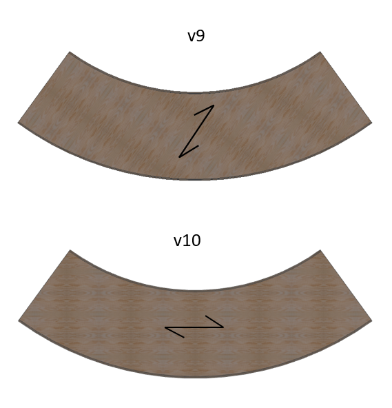
Typically, the part sizes are calculated in the direction that is automatically determined by the Woodwork for Inventor geometry solver. This set of keywords gives the sizes of the part according to the texture direction of the material.

{Item.Level} – Returns the item level in the Model Data Tree structure. It’s Either going to be 1, 2, 3 where 2 is two levels deep & 3 is three levels deep.

{Item.QuantitySum} – Returns the amount of components based on the number of times the assembly containing those components is repeated.

New Component Card View Template. Brings all the combinations of new and existing codes together.
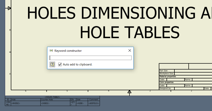
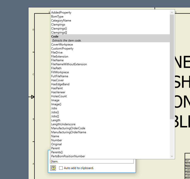
NEW Keyword Preview

Keywords can now be previewed by live generation when constructing in the BOM Specification without the need to export a spreadsheet. Enable by switching on the “Keyword Preview” .

Enable Keyword Preview & move from the bottom of the grid to an appropriate column position.

The Keyword Preview box will appear.

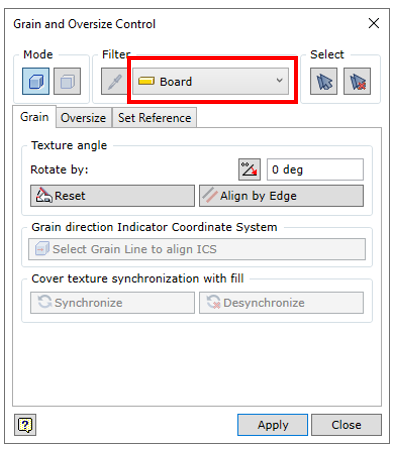
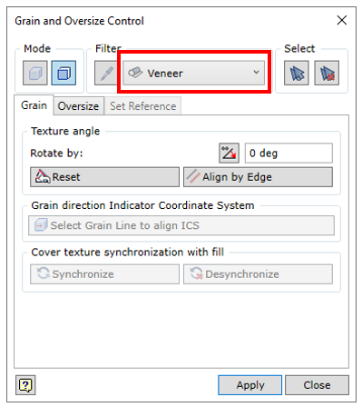
Try typing a value using a keyword such as {Material.Type} and it will report Board etc after selecting the generate icon

ADDITIONAL KEYWORDS

{Item.Sizes.PartByGrain.Length} – allows you to obtain the dimensions of the part according to the direction of the texture.

{QrCode({Item.Code},174)} – Create a QR Code

{BarCode.Code128(Item.Code)} – Create a BAR Code

{Item.DrawingImage(174)} – Attach Drawing Image

{Item.CoverWorkpiece.Top.Legend} & {Item.CoverWorkpiece.Bottom.Legend} – Reports Top &/or Bottom Cover
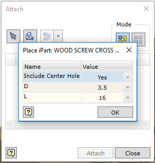
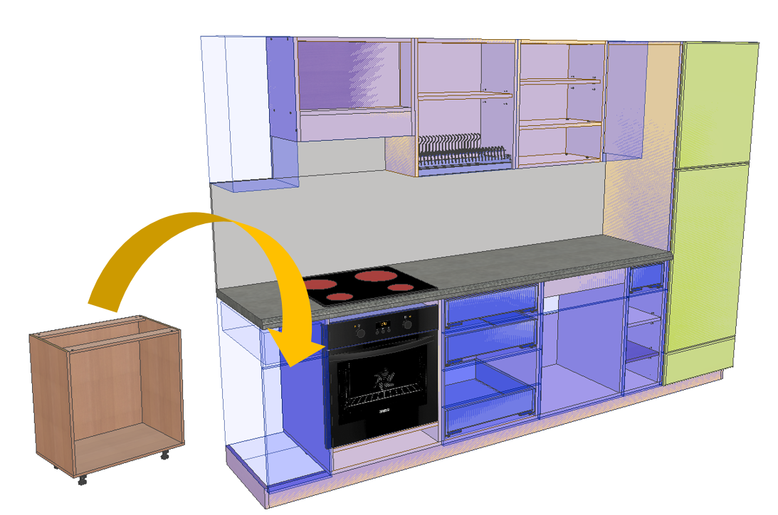
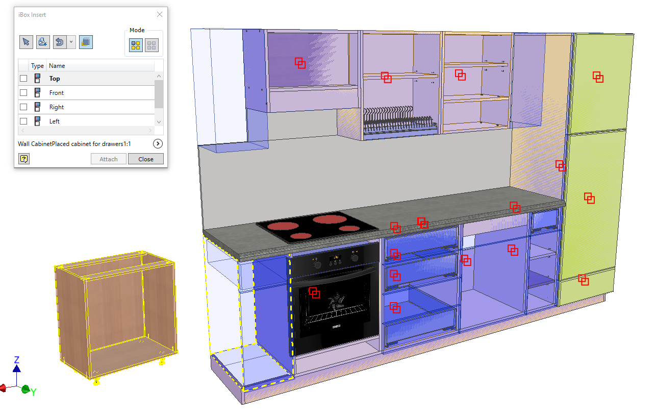
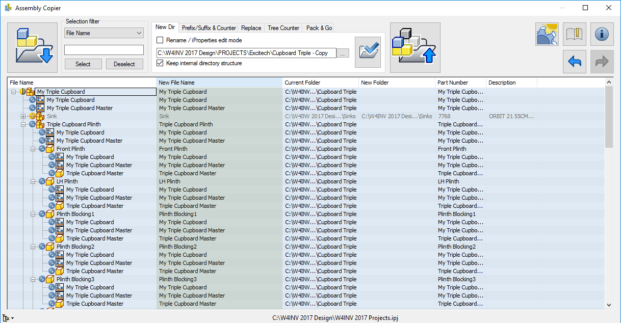
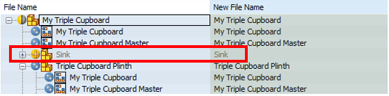
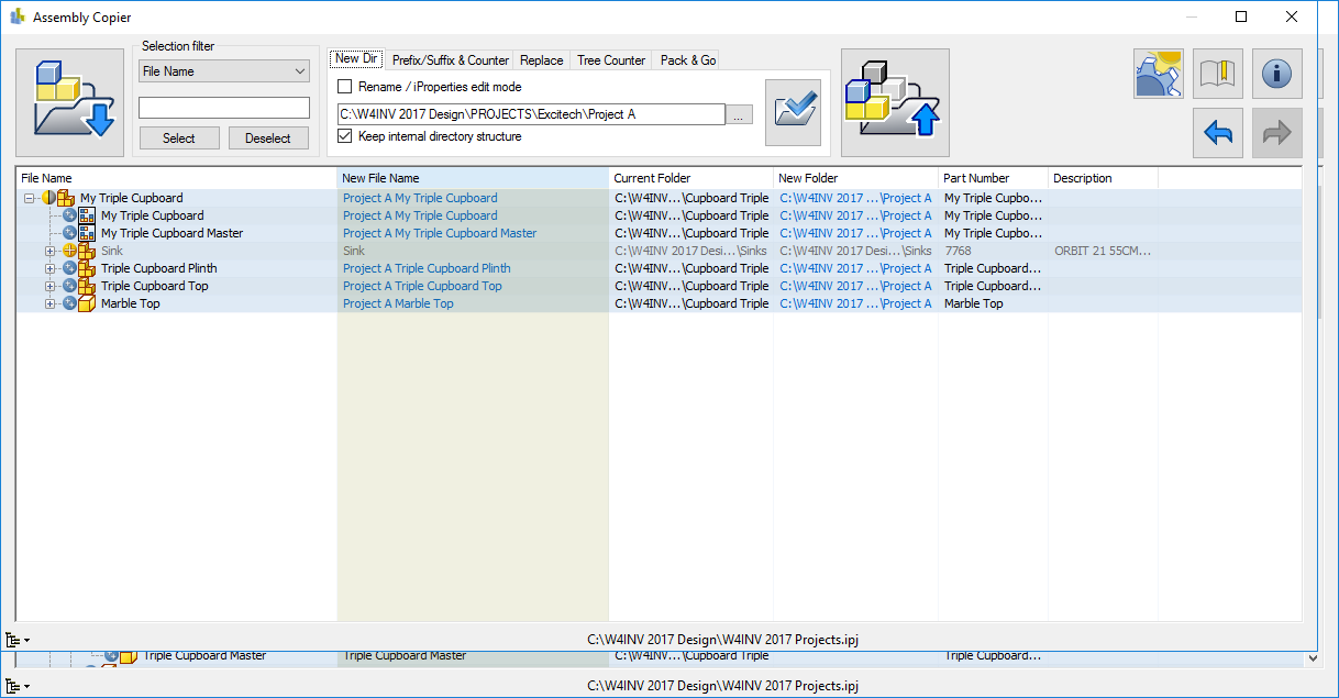
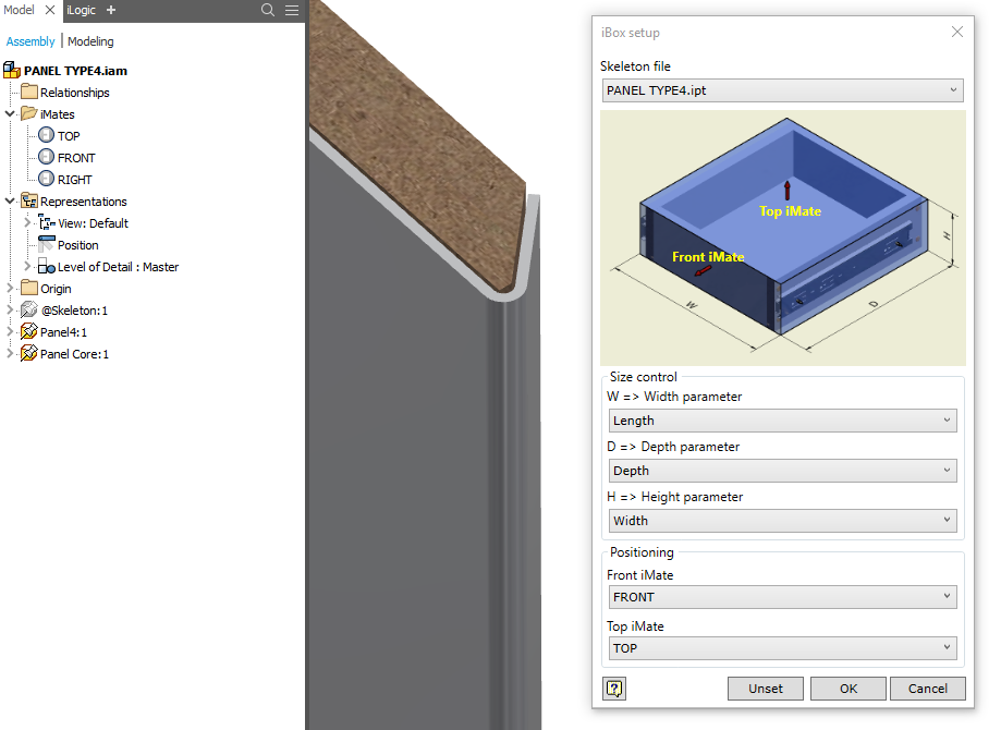
iBOX SUB FOLDER

You can now specify another sub folder to store your created iBOX components rather than placed in the root of the main assembly.

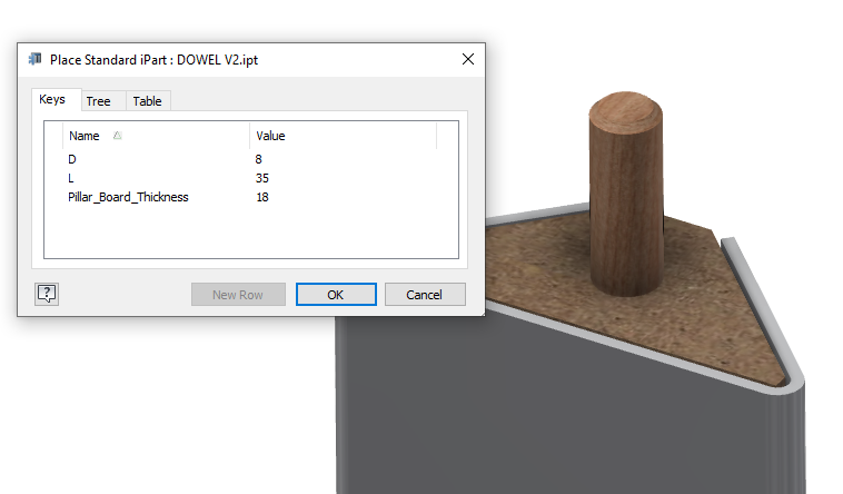
HOLE NOTES EMBEDED INTO HARDWARE

You can now import Hole Note data into W4i Hardware and automatically display this in your sculpted parts.

Use the Setup to launch the Hole Setup dialogue.

You can now create pre saved hole configurations that can be written into you hardware.

To write the hole data into the hardware parts (have to be in a read/write are of your project) simply select the solid body and Apply to hardware.

The hole notes will be displayed in your parts after sculpt is used on your assembly.
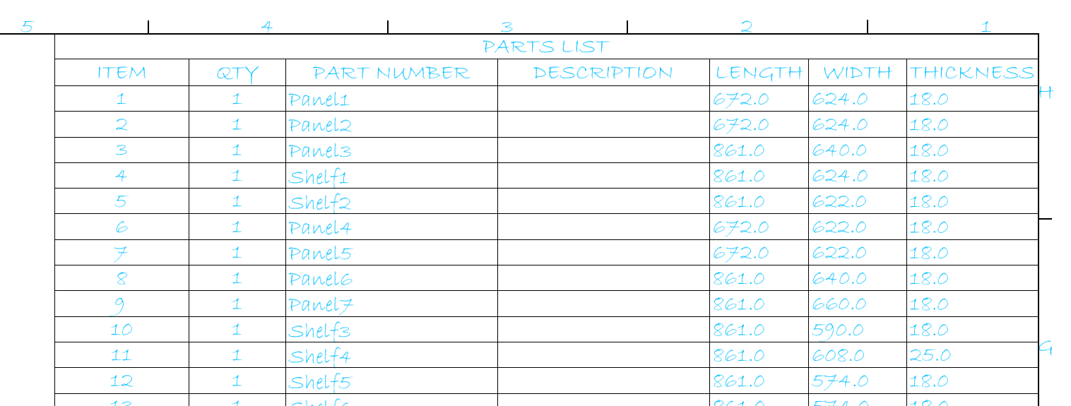
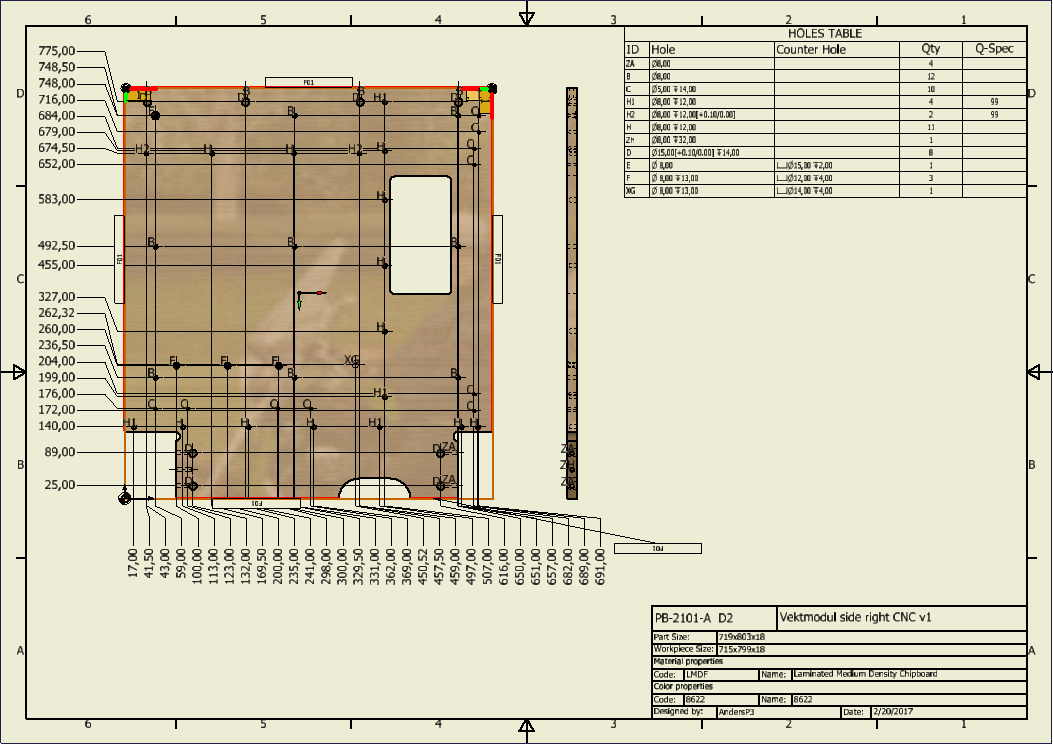
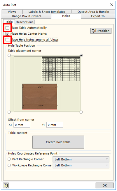
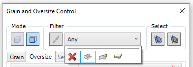
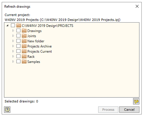
TABLES IN DRAWINGS

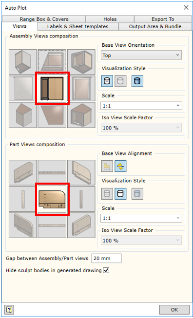
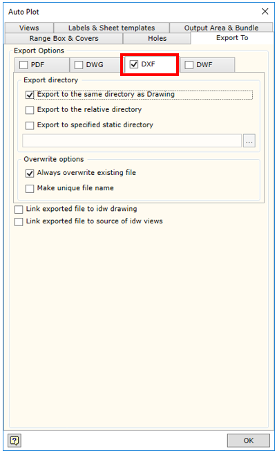
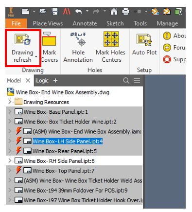
You Can now define tables within the AutoPlot output. Using the AutoPlot settings, Assembly & Part drawings are affected.

We have configured an Assembly BOM & Hardware BOM and for Parts we have configured the Material composition to be displayed.

When the AutoPlot routine is run you will see the table styles applied. You can remove the Tables by simply selecting the red cross.
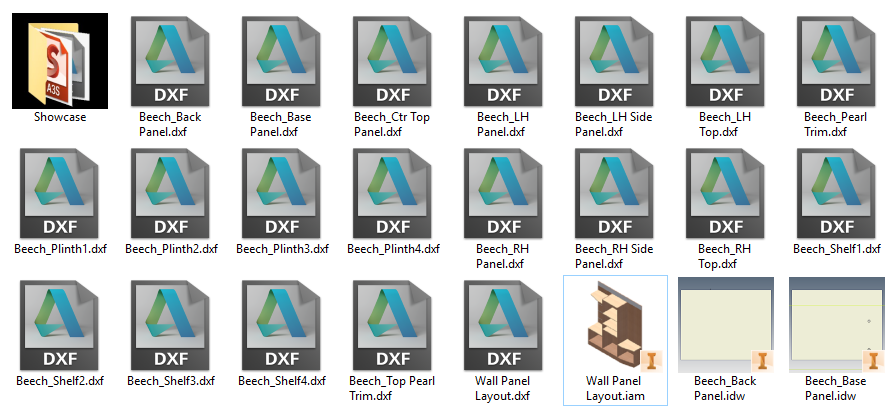
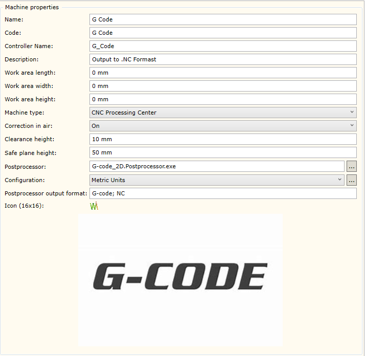
CAM

  • Updated Post Processors – Ongoing
Dxf
AlphaCAM DxfdxfAlphaCAM
AutoCAD DxfdxfAutoCAD
TwinCAM DxfdxfTwinCAM
Biesse Works
BiesseWorks1.5ProcessorBiesseWorks 1.5
Cid3BiesseWorks
Cix3BiesseWorks 1.5
G-code
G-code_2Dnc,cnc,ancAny G-code software
G-code_2DforMach4nc,cnc,ancAny G-code software
G-code_2DforMultiCAMcncAny G-code software
G-code_2DforOmnitechancAny G-code software
G-code_2DforOsainc, cncAny G-code software
G-code_2DforSyntectap, cncAny G-code software
G-code_2DforWoodtechtap, cncAny G-code software
ImaWop
ImaWop3fmcImaWop 3.0
ImaWop6fmcImaWop 6.0
Imawop8fmcImawop 8.0
Xilog
MaestroScriptingLanguagexcsXilog, Xilog Maestro
Xilogxxl,pgmXilog
XilogMaestroxxl,pgmXilogMaestro
Kochboh
MasterwoodtlfMasterwood
ShopBot_2dsbpShopbot
WoodWOP5mprHomag
GannomatasciiGannomat
Hops5hopHops
Cnidat
Cobus_Ncad_XMLxmlCOBUS NCAD
Format4tcn,cncTpaCad
  • Sizing Operation with Saw
  • Pocket Operations with islands
  • Simulation when correction on air is disabled

Official What’s New Video by Igor Borodovskij can been seen below:

What’s New Woodwork for Inventor v10

What’s New Woodwork for Inventor v10

It’s got a new logo but the devil is in the detail. This release excels by building on it’s foundations to deliver some impressive enhancements.

Enhanced Grain Direction Control

You can now Control grain direction on multiple panels. Adjust covers or material fills all in one go.

Before Rotated Grain

Rotated Grain

More control is achieved with the new layout dialogue.

Fill RotatedCovers Rotated

Over size Control Enhanced

Oversize5

Multi panel or edge over sizing can be achieved working similar to the grain direction control.

NEW Over size for Slant faces

You can now set an allowance for over sizing  slant edges on a panel globally. Located under Woodwork for Inventor Settings > Design tab

Slant Ovesizing

Increasing by 20mm as the example shown below.

Slant Oversize set to 20mm

Enhanced Texture Direction Indicators

Enhanced indicators show panel orientation and grain direction.

New GD Indicators


Optimise Part Orientation for grain direction

When applying a texture to a curved part in v9 it orientated along the x axis by default. You would then need to adjust the orientation to meet the longest edge requirement. Now  in v10 it will orientate the grain direction along the longest length of the bounding box which gives you more accurate BOM specification results.

Automatic longest length orientation for grain

Enhanced iBox Copy design support

iBox now aligns with the Autodesk Vault Copy Design process with a unique identifier for it’s base component. When renaming your files this will not interfere with the iBox functionality.

Auto-select base component

The skeleton file is now automatically selected when authoring an iBox. Note the new Unset button next to the OK button at the base of the dialogue box.

v10 iBox Enhancement

Enhanced Hardware Library

v10 iparts now support custom lengths as well as support for materialsv10 iPart support

Enhanced Material Library

Painted panels are now reported in the BOM Specification as a single line item rather than every face as was previously available with v9. This is a much faster method when radius edges are used on panels or even when 6 edges are required. You can still use Single Face option if required.

v10 Paint all Faces

Extended BOM Specification Hierarchy 

New templates are provided to facilitate in passing data to ERP systems. these are found in C:\Users\Public\Documents\Woodwork for Inventor\2019\v10\BOM Templates.

NEW Work-piece Angle Cut

Two new keywords have been made available for you to add these cuts to your BOM specification template. They are here for you to copy and paste into your template:

{item.FillWorkpiece.Left.CuttingAngle()}

{item.FillWorkpiece.Right.CuttingAngle()}

Accelerated BOM Specification Output

15-20x faster export to Excel. If there was one reason to upgrade to Woodwork for Inventor v10 it would be this alone. You will notice the difference. Nice job team!

Enhanced Drawing Environment

Refresh content of a selected folder

Drawing Refresh Icon

Drawing Refresh by folder

Refresh only selected sheets option within Inventor’s Browser or via the Project dialogue. This speeds up the drawing update process when single sheets may contain large number of feature parts.

Drawing Refresh Selected Drawings by Browser

Drawing Refresh Selected Drawings

Access Drawing Settings when refreshing drawings.

Settings Button Drawing Refresh

Drawing Refresh Settings v10

New BOM Position number keyword – Latest link to all Keywords can be found here http://help.tools4inventor.com/doc/Keywords-for-Woodwork-for-Inventor-V10.pdf

Enhanced CNC

Post Processor Support added for:

  • ShopBot 2D
  • Cobus NCAD xml

Enhanced SIZING operation can be applied automatically when assigning material. & over sized clamping options can be selected manually.

New Tooling Simulation Pre-Manufacturing Check

Simulation.png

Assembly Copier

Assembly Copier v10

The drawing name  now matches the component name when copying an assembly.

Naming Assembly Copier v10

If you have a Level of Detail with suppressed components, they are now included in the copy.

What’s New Woodwork for Inventor v9

What’s New Woodwork for Inventor v9

This new version of Woodwork for Inventor v9 (available for Inventor 2017, 2018, & 2019) building on the foundation of v8, this release refines what is already a proven platform for anyone looking to improve their design to manufacture process.

It’s been just over two weeks since the launch of v9 (Officially 2nd May 2018, 13:00 GMT) and thought it was about time I’d share with you my thoughts on this new release.  V8 saw some real power functions added to the software. In this v9 release, it’s all about refinement and making a good product great!

The developers have focused on 10 key areas:

Summary of What’s New & Enhanced

  1. NEW – Material Replacement
  2. Enhanced – Edge Banding in BOM
  3. NEW – BOM Keywords
  4. NEW – Keyword Constructor
  5. Enhanced – CAM Module
  6. Enhanced – Pocketing Algorithm
  7. NEW – G-CODE Post Processor
  8. NEW– JSON Platform
  9. NEW – Databases Merged
  10. NEW –  Assembly Copier

1. Material Replacement

With previous versions we could access the replace material command from within the BOM Specification environment and replace the material codes and names.

v8 Replace Materials
Previous access to Replace Materials in V8

Now it sits alone in the ribbon as a standalone toolReplace Icon and can replace the material or material colour. Simply select via database or the materials in the current model.

Material Mapping
New Material & Colour Tool in v9

Options
Quickly configure material & colour options across an entire design

Watch an overview Video

Additionally, it can be used in Bill of Material (BOM) environment, as in the previous version. Simply select the material icon or if you wish to configure a different hardware setup choose the hardware icon.

Access from BOM v9 replace materials


The model is updated as well as the drawing bundle and any BOM specification generated.

2. Edge Banding in BOM

The user has much more options to specify the edge band legend (visualisation) in the BOM generated for the item. Now the user can request not only for the visualisation of the edge bands placed directly on the component’s edge that borders with the surrounding box, but also the edge bands that border with the edge of a surrounding box. The bordering type can also be generated: Coincident, Tangent, and Point. This makes it easier for the user to navigate the Bill of Material (BOM).

3. BOM Keywords

New keywords for Bill of Material (BOM) have been entered. It define the part’s shape and its coating. Now the user will be able to see whether the part is rectangular and if it contains holes, edge banding, etc. in Bill of Material (BOM) Specification.

4. Keyword Constructor

A new keyword prompter called Keyword constructor has been implemented.

Keyword Constructor

While editing the Excel BOM or drawing templates, the user has an option to use keyword constructor which allows for generating the necessary keyword eliminating syntax errors.

Keywork constructor List

These keyword strings can be copied to the clipboard and pasted into the location within the template. It reduces the time required to adjust template forms.

5. CAM Module

The automatic functioning of CAM module has been improved. Now different setting options can be configured for several CNC machines with one post-processor.

6. Pocketing Algorithm

The pocketing algorithm has been corrected in the CAM module. A correction has been made to the calculation when milling an open pocket edge.

7. G-code Post Processor

New G-Code post processor has been created. Although this post had a sneek preview in W4I v8 if you were looking in the right place.

G-Code

8. JSON Platform

The Woodwork for Inventor database has been migrated to the JSON platform.  Now the data service does not require the SQL compact driver.

Performance over a shared network and database locking for editing are just two great reasons this has been implemented. It’s fast….

Json

9. Databases Merged

Woodwork for Inventor materials, CNC machine database, and CAM behaviour settings are merged into a single database which helps facilitate certain interaction issues between Woodwork for Inventor materials and CNC machines. Also, it increases the overall operational reliability of the system.

10. Assembly Copier

Assembly Copier

The Assembly Copier function has been re-written for Woodwork for Inventor v9. Various linked files can be included in the list of copied items. Therefore, various MS Excel image-type linked files become items that can now be copied. This gives the user much more flexibility in adjusting the behaviour of the Assembly Copier.

Overall, we are now able to utilise the power of Inventor 2019 and this release seems to bark refinement & speed. Well done Woodwork for Inventor Team!

How to get Multi Body Part Length, Width & Thickness into Inventor BOM & Drawing Parts List

How to get Multi Body Part Length, Width & Thickness into Inventor BOM & Drawing Parts List

When creating Autodesk Inventor Multi Body Solids, you would like to place a Cutting List on your drawing that matches the Woodwork for Inventor BOM Specification? Is this possible? Yes. You can do this with the Woodwork for Inventor property mapping tool.

This tool can map Inventor custom iproperties to the Woodwork for Inventor BOM specification but can also write back from the specification to create you a custom iProperty. In this example we are going to write properties from the Woodwork for Inventor BOM Specification back to Inventor iProperties.

If you have an assembly model after using the make components and you have created custom iproperties for Length, Width & Thickness. They will be blank.

Assembly Bom

Check your part and they will not exist. In this example I have a few properties already created.No Custom iProperty

The magic happens after setting up the mapping within the Woodwork for Inventor Settings > BOM tab.

display-cover-direction-and-colour-4

Launch the Design Settings from the Woodwork for Inventor Ribbon.

Setup Mapping Default

The dialogue will be blank as above, so now time to add specific mappings.

Setup Mapping

You should start in the right hand box and drive the Woodwork for Inventor Property back to Custom iProperty.

{Item.Length} Maps to LENGTH

{Item.Width} Maps to WIDTH

{Item.Thickness} Maps to THICKNESS

It’s important to enable the ability to write BOM data after Woodwork for Inventor BOM specification is closed and on save. So tick those boxes.

With Custom iProperty

If you check each part you will see the iProperties have been created.

Assembly Bom Filled
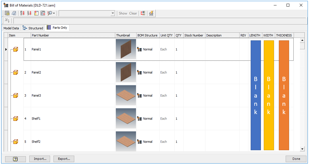
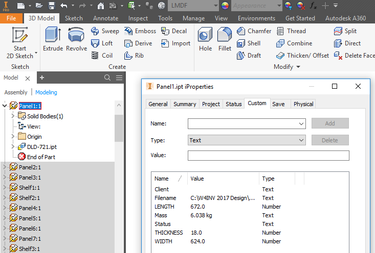
Now checking your Assembly BOM, the data will now be filled in. You can now also check your drawing Cutting List.Drawing Cut List Filled

There are a number of other keyword codes you can map can be found in the full list of keywords available http://help.tools4inventor.com/doc/Keywords-for-Woodwork-for-Inventor-V7.xlsx 

What’s New Woodwork for Inventor v8

What’s New Woodwork for Inventor v8

This new version of Woodwork for Inventor v8 (available for Inventor 2015, 2016, 2017 & 2018) is an exciting release and well worth the wait. So let’s start with what I can honestly say will revolutionise the way you think about creating and using a template carcass in your assemblies.

Layout1

Forget your parameter linking, icopy, adaptive shenanigans! It’s time to use the new Woodwork for Inventor iBOX tool! it sounds small, but believe me it packs a punch, when you hear what it can do. In fact, It’s already got me thinking how easy we could utilise Revit model layouts. More about that later.

Another area that has seen some long awaited attention is to be able to generate a nest of panels in the CAM version. Nice job guys, this certainly keeps everything tight and integrated in the package. So let’s dive in….

Summary of What’s new

Dress Up Function NEW Panel Mitre
Materials NEWReplace material tool for model & BOM replace in specification
Drawings NEW – Can use DWG in AutoPlot, Hole Tables enhanced, Automatic visualisation of hole parameters in a drawing and changing the hole table form.
Visualisation of the information created by the Woodwork for Inventor add-on in the drawings created by the user.
Parts NEW3D hole annotation
Assembly NEW – iBox & enhanced Attach command
CAM NEW – Preliminary Nesting & Improved automatic clamping detection

Panel Mitre

An extension to the Skeleton Dress up capability, we can now mitre panels together in addition to the normal trim. All ready for further jointing methods such as adding biscuits.

Mitre Trim

Replace material tool in the model

Simply change all used materials in the model with a different material within the apply material dialogue box. This great addition makes swapping out materials a whole lot easier.

Material Replace 1Material Replace 2

Pre-set material over-size

While creating a material, the user now has the option to pre-set the workpiece over-sizing. With this feature you do not need to assign an over-size as a separate command afterwards because it is applied when the material is assigned.

Material Oversize pre-set

Improved material and colour replacement in the BOM specification

The user can now link each type of material to Excel tables. This improves the application and provision of data replaced in MS Excel tables for each material type and facilitates navigation in MS Excel table entries.

Map Materials

Automatic visualisation of hole parameters in a drawing

The automatic plotting of drawings now allows the users to request automatic export of hole position parameters into the part drawing.
Hole Table

Changing the hole table form

The user can create his own hole table templates in the Woodwork for Inventor drawing template based on which of these tables will be generated in the drawing. This ensures that the form of the hole table being generated are better suited to the user’s needs.

Attach tool enhancement

When attaching iPart configured hardware using the attach tool, you will now be prompted to enter the ipart configuration on placement.

Insert Enhancement

iBOX Components

You can now author iBOX assemblies to use in concept layouts. Either create your own inside Inventor or you can leverage the solids created from other 3D packages such as Autodesk Revit.

This example could be a parametric concept layout of a Tea Point or Kitchen. We can define simple volumes that outline where cupboards would go, drawer positions and door spaces.Kitchen Concept1

By using insert ibox tool Insert iBox, you can quickly place your template cabinet and it will automatically size itself to the space indicated.Kitchen Concept2

Follow the prompts and select the sold first then top, front and right faces.

Kitchen Concept2.2

Job done! It’s easy and each unit will be unique to amend further using the embedded iLogic.

Kitchen Final1Kitchen Final2

So this got me thinking, what if we imported a kitchen layout from Autodesk Revit? I used the standard Architecture model in this example. Quite simply yes you can, you get the bounding box of the unit as well as drawer fronts. I did some restructuring of parts in the Inventor browser to make some sub assemblies and general folders to group together parts.

Add your carcass (Woodwork for Inventor  comes with a selection of ready built cabinet templates so used the sample iBox Insert iBoxmodels here but you can create your own). However, these models had 100mm plinth details and the Revit model cabinets terminated at the finished floor level. I moved the bottom face of each Revit imported body using Inventor’s direct edit tool -100mm and after an iBox refresh Refresh iBox all cabinets updated. So it doesn’t matter where your layout comes from. If inventor can import it then you can save a lot of time taking your concept to manufacturing.

Quick iBOX

I’ll cover this workflow in more detail in a future blog post.

CAM – Nesting

You can create CNC technologies for all parts which are suitable for the CNC nesting router machine, and later combine them and create a common nesting program for cutting parts from a single sheet of material. In this environment, individual CNC part technologies can be moved, turned, transferred to a different sheet, etc.

Nesting.png

Improved automatic clamping detection

The clamping detection algorithm in the automatic CNC technologies has been improved. The user can now indicate more criteria that influence the automatic clamping option. For example, the user can set basic reference planes for all parts of the product, taking into account their orientation within the product. It is possible to set assessment weight for all the criteria, in this way adjusting their impact on the clamping selection. This adds more accuracy to the automatic creation of CNC programs performed by the Woodwork for Inventor add-on.

Let’s AutoPlot

Let’s AutoPlot

In this Blog post I thought it was time we took a look at some tips around the drawing environment of Woodwork for Inventor.

Anyone who has used Autodesk Inventor will know that you can save a drawing to DXF. However, this only works when using .DWG templates and we use .IDW which we want to automate on save.

What is DXF? Autodesk wrote the standard. way back in December 1982 when they launched AutoCAD and needed data interoperability between other systems including AutoCAD and called it Drawing eXchange Format otherwise know as DXF. It’s a vector based output used by many 2D CAD systems today and the original plan was to allow for Import as well. In the last decade we have seen the availability of 3D DXF.

So let’s take the scenario:

You have a built 3D model and you require a set of DXF files to be created.

  1. Scale = 1:1
  2. One panel = One DXF file
  3. Annotation such as dimensions, edge banding annotation removed
  4. Profile has to be the workpiece size and part size
  5. Holes & cut-cuts must be included

autoplot

Select AutoPlot from the Woodwork Ribbon.

autoplot-choose-template

Choose the template required as the basis for the AutoPlot. We are going to choose Each Component to separate File.idw.

templates

At any point you can save your changes which will be written to your template. I would recommend saving with a suffix of DXF to the file name so you can keep your original template file.

dxf-options-2

Set the views tab to have scale 1:1, plan view for part. As we really want the DXF file in this instance the Inventor drawings won’t be used so it won’t matter if you leave the view set to rendered.

dxf-options-3

On the Labels & Sheet templates I’ve set all symbols to Do Not Plot. The template tabs are also blank because the title blocks and borders have been deleted. It’s optional if you want to leave the title block which would have material info contained.

dxf-options-4

Uncheck place table automatically and place hole notes among all views.

dxf-options-5

Select the Export To tab and DXF options. You can preselect where to save your DXF files if required.

dxf-options-6

For the Range Box & Covers tab make sure both part size and work piece size are set. Un-select place veneer, edge band and paint curves.

no-title-block

Delete the title blocks and borders

dxf

Save your template by giving it another name. Now simply execute the Auto Plot and you will get multi file Inventor Drawings with a DXF.

output1

You can verify using AutoCAD if required.

w4i_dxf


Copying Assemblies

Copying Assemblies

You have an assembly completed and it’s destined to be a master template. It’s the same only different!

same-but-different

We’ve all done it. Used windows explorer to copy a folder with some Inventor models, tried to rename them and when we open the assembly Inventor is griping “resolve referenced part”.

Well there are several ways of approaching this; you could use Pack and Go, Inventor Design Assistant or even go the full Monty with Autodesk Vault. Well, Woodwork for Inventor comes with it’s own simple but highly effective in built assembly copying tool called Assembly Copier.

Use in context of the assembly Window.ac1

Or, can be launched from the Windows Desktop

ac2

Allows to rename & update properties a copy to new location with a single click.

master1a

Let’s copy this Vanity unit.

Assembly Copier Dialogue

The Assembly Copier ignores library parts automatically if they are stored in the woodwork for Inventor Library.

ac4

You can rename, choose new file location ect. Here I have prefixed my template with Project 1 after using the replace for My.

ac5

TIP. You can now select the New File Name column and whilst you have the first mouse button selected simply release over Part Number column and a prompt will appear to allow you to copy the new filename to part number.

ac6

Initiate the copy

ac9

You will now see a report.

ac7

Execute the copy.

ac8

You can make your changes and launch your new design directly in the Inventor graphics window perform your changes and save.

copy-1

Here is a comparison vs Vault Copy Design and iLogic Design Copy / Design Assistant

assembly-copier-table

Have fun!!


Insight to Woodwork For Inventor – Software for Woodworkers 31st January 2017 – On Demand Webinar Available

Insight to Woodwork For Inventor – Software for Woodworkers 31st January 2017 – On Demand Webinar Available

This webinar introduces you to the benefits of  Woodwork for Inventor and Woodwork for Inventor CAM for the Joinery professional.

Part 1 – General Introduction

Modelling strategies, Materials, applying, grain direction, Edge Banding, BOM Specification

Part 2 – Value in standardising components and automated drawings

Adding hardware, adding custom components, multi cut drilling, Joints, Automatic Shop Drawings

Part 3 – Introduction Woodwork for Inventor CAM

Processing Individual Parts, Job Setup, Clamping, Operations, Program Output, Automatic Assembly Processing

woodwork-for-inventor-webinar-31st-jan-17-v2

http://www.excitech.co.uk/Insights/Thought-Leadership/Webinar-Recordings/WWFI-Webinar