Time to reflect and look forward to a better year in 2021.
All the best,
Graham

Time to reflect and look forward to a better year in 2021.
All the best,
Graham

Below is a useful list of Improvements and fixes added to the current release.
Woodwork for Inventor 11.1.0 (Release date: 2020-12-08)
Woodwork for Inventor 11.0.2 (Release date: 2020-06-03)
Woodwork for Inventor 11.0.1 (Release date: 2020-05-18)

There are times when you have parts in your assembly that do not have W4i materials assigned. Sometimes this is as designed but sometimes if parts have been mirrored for example they will look like they have the W4i materials applied but W4i is lying to you. You probably won’t find out until you export your BOM specification and worse miss them altogether. Especially if it’s just 1 or 2 parts.
To check you have them covered, enable the W4i BOM setting check for “Normal” type parts without Woodwork materials.

Run the Woodwork BOM Specification tool and if you have any parts without materials you will be told. Without this enabled you will never know!


Woodwork for Inventor was released back in May this year and I haven’t really had time to review this release in earnest due to other priorities. A major Pandemic springs to mind and sometimes, life just gets in the way. Anyway… until now, so here goes.
ADAPTIVE SCULPT

Before v11 the Sculpt tool has always been a useful tool to remove material or even add material to your parts at the assembly level. Up until now, we have had to manually re-sculpt our assemblies once a parametric change has occured otherwise the cutout would remain in the original position.

Now with v11, the sculpt tool can now work in unison with your parametric changes. How? Adaptivity is how. In W4I it’s been called “Associative”.


By enabling “associative” when creating your sculpt, it will automatically set all affected parts and sub assemblies to become “Inventor adaptive”. Should you wish to revert back & remove adaptivity then removing your sculpts will not clear the adaptivity flags set. You will need to manage these manually by right clicking the parts in the model browser and switch off. If the parts are buried in a sub assembly you will need to open the part and clear the adaptively used in assembly button under Tools> Document Settings. It’s worth taking some time to understand more about the pros & cons of using adaptivity.
Extract about Adaptivity from the Autodesk Inventor Online Help system <Click Link>
MULTILAYER BOARD MATERIAL
This interface is now overhauled to make it easier to create Multilayer Boards. You now have the choice to create a local material added to the part or a sharable material added to the W4I material database.

A typical scenario might be making up a composite worktop. 12mm Corian on the top with an 18mm sub-top made from MDF, however you need a bonding zone of 2mm for Adhesive.

The buildup will require you to have the W4I materials you want to assign already created in your own read/write library. You can then store the custom Multilayer material in the local part or share in your custom library. Two new icons have been provided to choose the Material Origin.


The output can be seen on the AutoPlot where the breakdown matches your described build up and of course the BOM Specification.

REPLACE MATERIAL (Configuration)
Material & hardware replacement tool interface has been updated to make it easier to understand what’s applied and to ensure you now have the option to lock the configurated material into the part. The intent behind this tool remains the same as it was when first introduced. You have a design as a default but wish to vary the applied materials via a customer request and potentially source alternative hardware. The dialogue box now only shows current materials which includes the modified materials.

To use the Replacement Materials & Hardware you will need to configure the spreadsheet that is linked to the model. Here we are creating a New Configuration but it could be called Customer A, Customer B or Light Oak, Dark Oak.
Let’s take a look at these five steps.

Step 1. Choose Setup

Step 2. Navigate to locate your custom lookup spreadsheet. There is a sample Replacement data by Material type.xls available in the C:\W4INV 2019 Design\Projects\Samples\Replacement Data\Materials folder. This will give you an idea of how to build your own Company spreadsheet.

Step 3. Once you have connected the spreadsheet for this configuration you can map the Column Names as below Step 4.

Now you should see the mapped data pulling through into the dialogue box.

Step 5. Double click the colour image you would like to use and it will set the material for you.


You can be selective in which components can be modified by de-selecting the ticked items on the left of the dialogue. The material will only effect those components that are active when using the “Apply Appearance Image Replacement” button.
Once the material has been written into the part you can now lock that material and unlock if required. Write, does just that where it will assign the material and Clear removes the material allowing you back to default and to start again.

USED MATERIALS (Global change)
An undocumented new addition. You can now toggle the materials on/off/shaded/transparent with the addition of some new buttons in this release.


REFERENCE PARTS & ASSEMBLIES
Parts & assemblies that are flagged as reference in the Inventor BOM are now removed from the W4I BOM Specification whereas in v10 or earlier they did not. Why is this important? Using Reference flags on parts etc is normal workflow for Inventor users.

Take the example where you place a component such as a Glass clamp. The issue is, the part knows it comes as a set of 4 in a box when ordered but if you were to place them individually you would end up ordering 16.

Therefore, you need to place all 4 in the assembly to show pictorially and make 3 of them Reference.

When you run the W4I Bom Specification you will see a warning reminding you that there are reference components in your assembly.

The BOM Specification now reports correctly.

EDGE BAND LEGENDS
You can build your content for the cover legend

| Name | Inserts a keyword that exports cover material name into the template. |
| Code | Inserts a keyword that exports cover material code into the template. |
| Color Name | Inserts a keyword that exports cover material colour name into the template. |
| Color Code | Inserts a keyword that exports cover material colour code into the template. |
| Thickness | Inserts a keyword that exports cover thickness into the template. |
| Width | Inserts a keyword that exports cover width into the template. |
| Separator | Defines a separator that is used when descriptions of several types of edge bands have to be exported on the same side. |
| Coinsident to range box edge | Defines export of edges that coincide with the Surrounding Box. Export of this type of covers cannot be disabled. |
| Tangent to range box edge | Defines export of tangent edges that coincide with the Surrounding Box. |
| Point touch range box edge | Defines export of point edges that coincide with the Surrounding Box. |
| Indirect touch range box edge | Defines export of indirect edges that coincide with the Surrounding Box. |
| Prefix/Sufix | Allows specifying a prefix or suffix for the exported information about each type of cover. |
| Top Legend | {Item.CoverWorkpiece.Top.Legend} |
| Bottom Legend | {Item.CoverWorkpiece.Bottom.Legend} |
| Left Legend | {Item.CoverWorkpiece.Left.Legend} |
| Front Legend | {Item.CoverWorkpiece.Front.Legend} |
| Right Legend | {Item.CoverWorkpiece.Right.Legend} |
| Back Legend | {Item.CoverWorkpiece.Back.Legend} |

BOM SPECIFCATION ENHANCEMENTS
BOM by Products
Now the table definition (area between Table.Start; Table.End) can contain different data output templates Table.DataDescription, depending on the type of element being read from the Model Data Tree. Also, the output of the item data can be executed on more than one line.

Previous Size direction indexes which contains “X”, “Y”, “Z” letters should now be changed to “L”; “W”; “T” respectively.
For example should be changed to or -> You will need to modify your your report templates if using.
New set of Sizes is implemented:
{Item.Sizes.PartByGrain.Length}
{Item.Sizes.PartByGrain.Width}
{Item.Sizes.PartByGrain.Thickness}
| Length | Width | Thickness |
| {Item.Sizes.PartByGrain.Length} | {Item.Sizes.PartByGrain.Width} | {Item.Sizes.PartByGrain.Thickness} |
| Length | Width | Thickness |
| {Item.FillWorkpiece.Sizes.L} | {Item.FillWorkpiece.Sizes.W} | {Item.FillWorkpiece.Sizes.T} |
Typically, the part sizes are calculated in the direction that is automatically determined by the Woodwork for Inventor geometry solver. This set of keywords gives the sizes of the part according to the texture direction of the material.
{Item.Level} – Returns the item level in the Model Data Tree structure. It’s Either going to be 1, 2, 3 where 2 is two levels deep & 3 is three levels deep.
{Item.QuantitySum} – Returns the amount of components based on the number of times the assembly containing those components is repeated.
New Component Card View Template. Brings all the combinations of new and existing codes together.

NEW Keyword Preview
Keywords can now be previewed by live generation when constructing in the BOM Specification without the need to export a spreadsheet. Enable by switching on the “Keyword Preview” .

Enable Keyword Preview & move from the bottom of the grid to an appropriate column position.

The Keyword Preview box will appear.

Try typing a value using a keyword such as {Material.Type} and it will report Board etc after selecting the generate icon![]()

ADDITIONAL KEYWORDS
{Item.Sizes.PartByGrain.Length} – allows you to obtain the dimensions of the part according to the direction of the texture.
{QrCode({Item.Code},174)} – Create a QR Code 
{BarCode.Code128(Item.Code)} – Create a BAR Code
{Item.DrawingImage(174)} – Attach Drawing Image 
{Item.CoverWorkpiece.Top.Legend} & {Item.CoverWorkpiece.Bottom.Legend} – Reports Top &/or Bottom Cover
iBOX SUB FOLDER
You can now specify another sub folder to store your created iBOX components rather than placed in the root of the main assembly.

HOLE NOTES EMBEDED INTO HARDWARE
You can now import Hole Note data into W4i Hardware and automatically display this in your sculpted parts.

Use the Setup to launch the Hole Setup dialogue.

You can now create pre saved hole configurations that can be written into you hardware.

To write the hole data into the hardware parts (have to be in a read/write are of your project) simply select the solid body and Apply to hardware.

The hole notes will be displayed in your parts after sculpt is used on your assembly.

TABLES IN DRAWINGS
You Can now define tables within the AutoPlot output. Using the AutoPlot settings, Assembly & Part drawings are affected.

We have configured an Assembly BOM & Hardware BOM and for Parts we have configured the Material composition to be displayed.

When the AutoPlot routine is run you will see the table styles applied. You can remove the Tables by simply selecting the red cross.

CAM
| Dxf | ||
| AlphaCAM Dxf | dxf | AlphaCAM |
| AutoCAD Dxf | dxf | AutoCAD |
| TwinCAM Dxf | dxf | TwinCAM |
| Biesse Works | ||
| BiesseWorks1.5Processor | BiesseWorks 1.5 | |
| Cid3 | BiesseWorks | |
| Cix3 | BiesseWorks 1.5 | |
| G-code | ||
| G-code_2D | nc,cnc,anc | Any G-code software |
| G-code_2DforMach4 | nc,cnc,anc | Any G-code software |
| G-code_2DforMultiCAM | cnc | Any G-code software |
| G-code_2DforOmnitech | anc | Any G-code software |
| G-code_2DforOsai | nc, cnc | Any G-code software |
| G-code_2DforSyntec | tap, cnc | Any G-code software |
| G-code_2DforWoodtech | tap, cnc | Any G-code software |
| ImaWop | ||
| ImaWop3 | fmc | ImaWop 3.0 |
| ImaWop6 | fmc | ImaWop 6.0 |
| Imawop8 | fmc | Imawop 8.0 |
| Xilog | ||
| MaestroScriptingLanguage | xcs | Xilog, Xilog Maestro |
| Xilog | xxl,pgm | Xilog |
| XilogMaestro | xxl,pgm | XilogMaestro |
| Koch | boh | |
| Masterwood | tlf | Masterwood |
| ShopBot_2d | sbp | Shopbot |
| WoodWOP5 | mpr | Homag |
| Gannomat | ascii | Gannomat |
| Hops5 | hop | Hops |
| Cni | dat | |
| Cobus_Ncad_XML | xml | COBUS NCAD |
| Format4 | tcn,cnc | TpaCad |
Official What’s New Video by Igor Borodovskij can been seen below:

I wrote this a while back but it’s still useful.
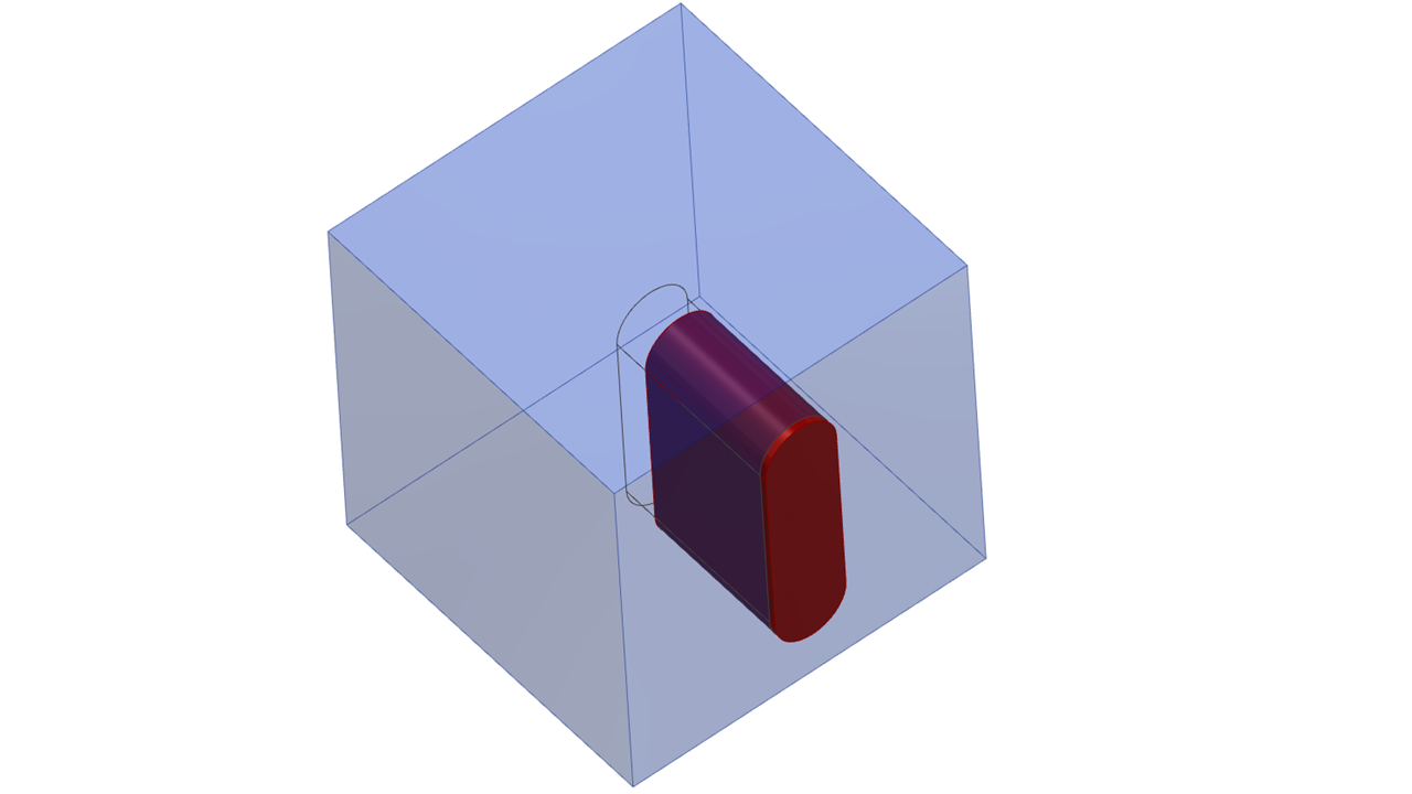
Tutorial to show adding a mortise & a tenon with a dowel hole at the same time. The Timber size that the joint will attach onto is 50×50.
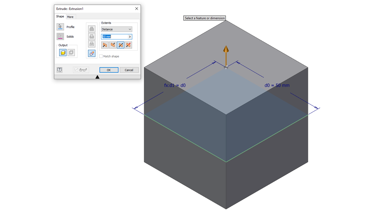
Step 1 – Sketch a rectangle 50x50mm about the sketch origin.

Step 2 – Extrude the rectangle symmetrically about the work plane 50mm
Step 3 – Create a new sketch on a side face and draw a slot as below, you can use the slot tool or draw your own if you want the practice. Make sure you key the parameters Mortise_Width = 10mm, Mortise_Height = 35mm and Mortise_Height / 2ul for half the height.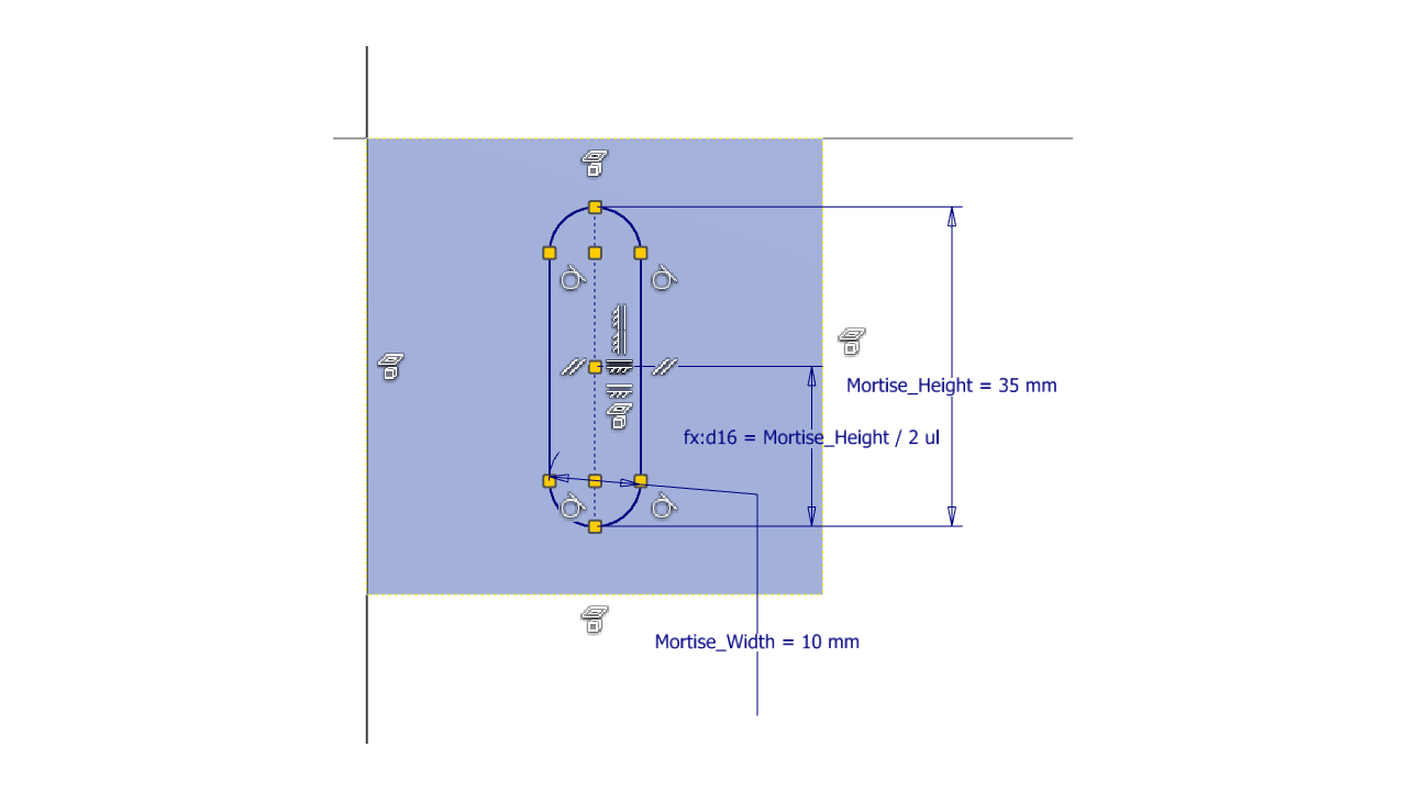
Step 4 – With a fully constrained sketch, you can Extrude the slot into the block 25mm but make sure you select New Solid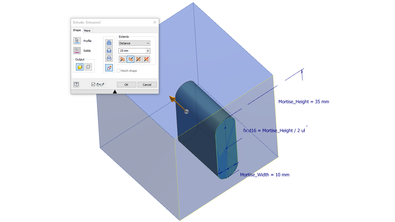
Before you select OK, you need to change the Extents Extrude to Asymmetric and have 1mm of the slot come out of the block as below. This 1mm will be joined to the mating timber and will be consumed into the part so you won’t see it.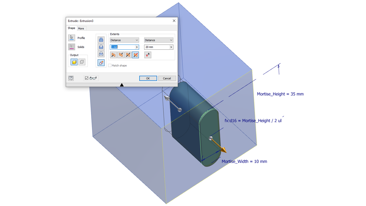
Select OK
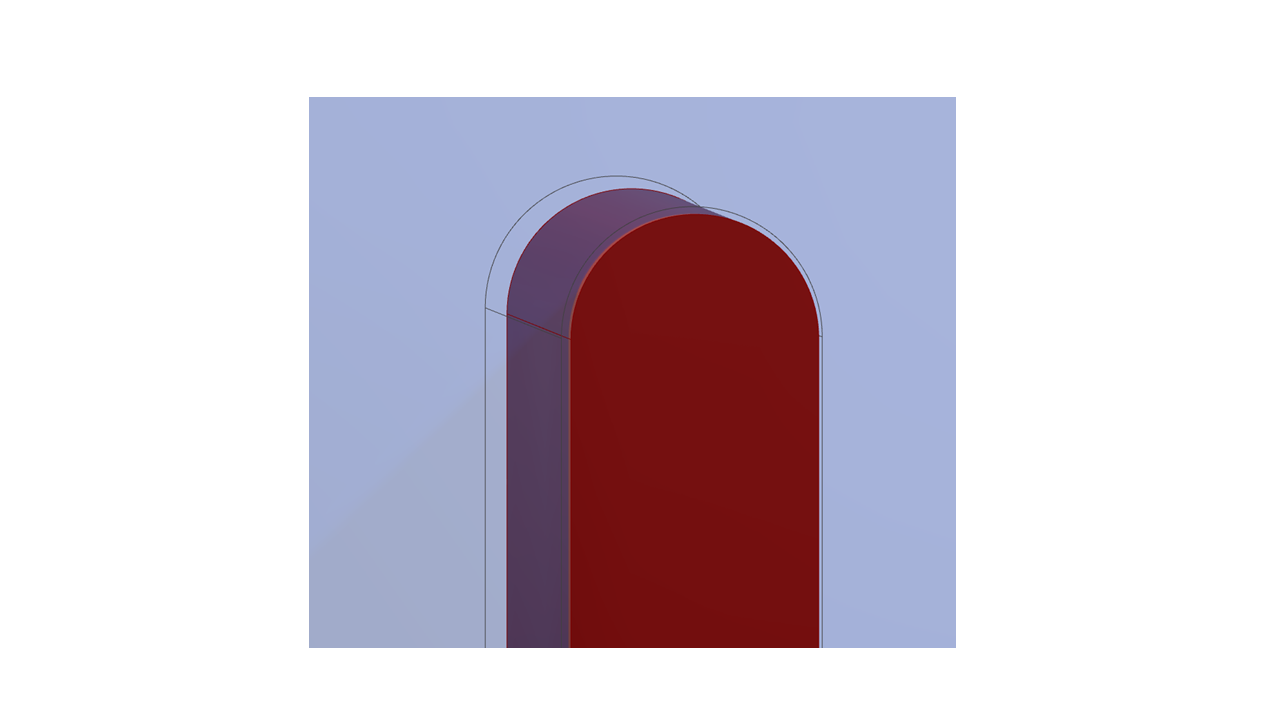
Step 5 – Now we are going to add some clearance around the joint. Use Thicken & offset 0.25mm cutting into the part.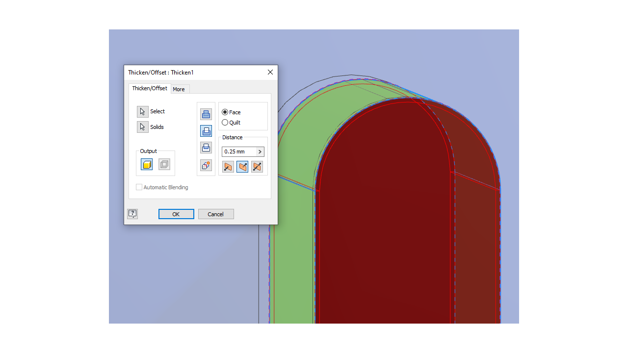
The Joint should be slightly smaller.
Step 6 – We now need to duplicate the work and create a second joint feature so sketch out the profile as before in Step 3.
Step 7 – Extrude the joint, but switch to asymmetric extrusion.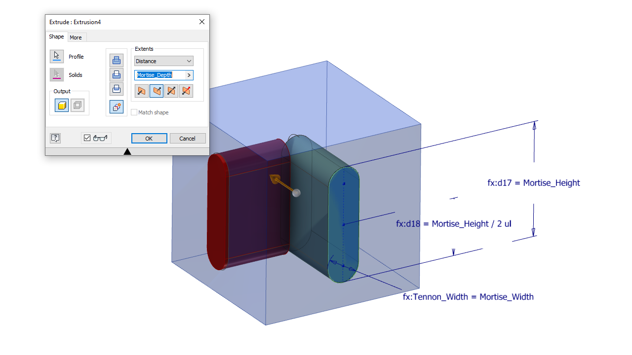
Set distance 1 to Tennon_Depth & distance 2 can protrude the 1mm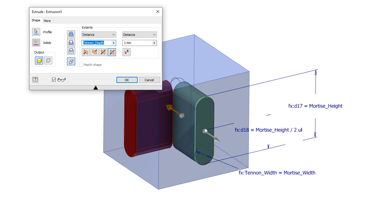
Step 8 – Now again, Thicken as before 0.25, cutting into the joint. 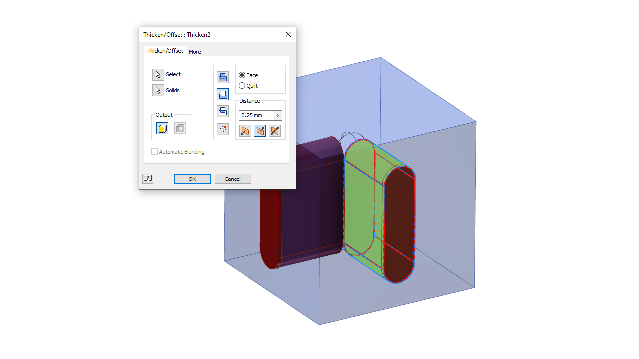
Step 9 – Create a sketch for the dowel hole which in this case I have just used a circle. You could use the hole command if you prefer. Dowel_Dia = 6.35mm, positioned 12mm x 6mm as below.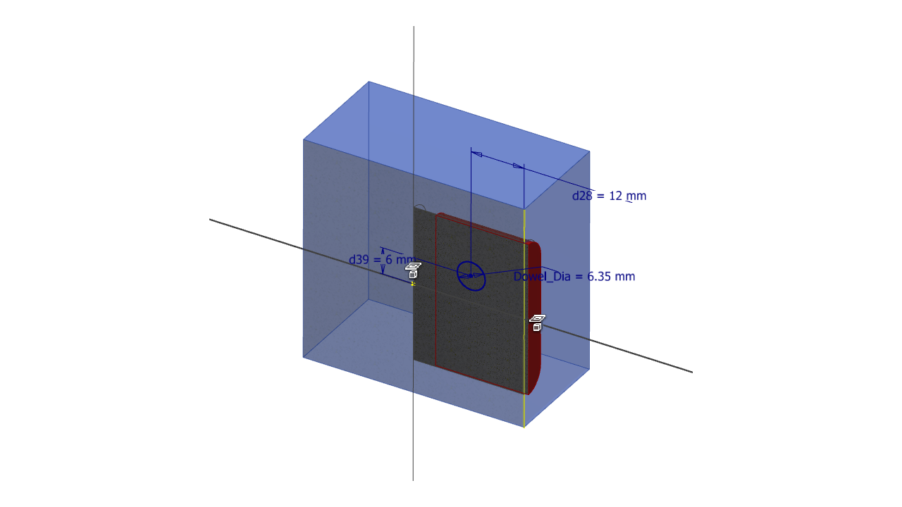
Step 10 – Now Extrude and cut through the joint.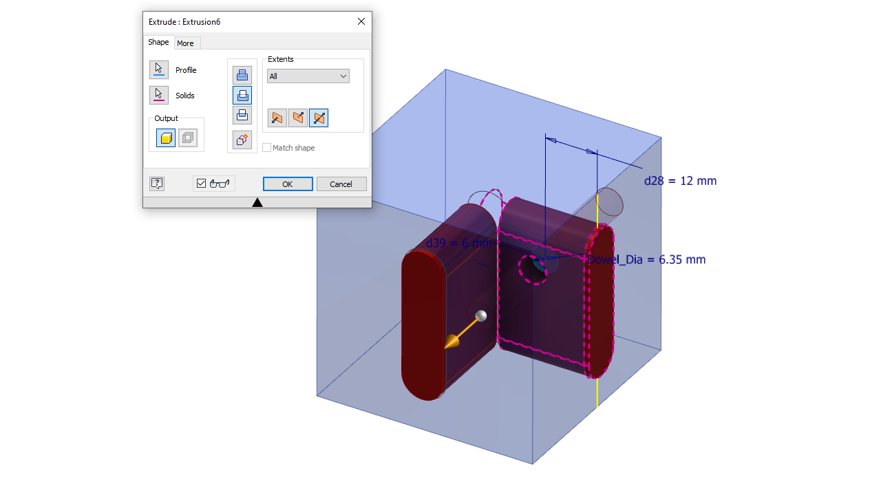
Step 11 – Create the Dowel. Share the sketch & create another extrusion between the two faces shown below. Make sure you select new solid.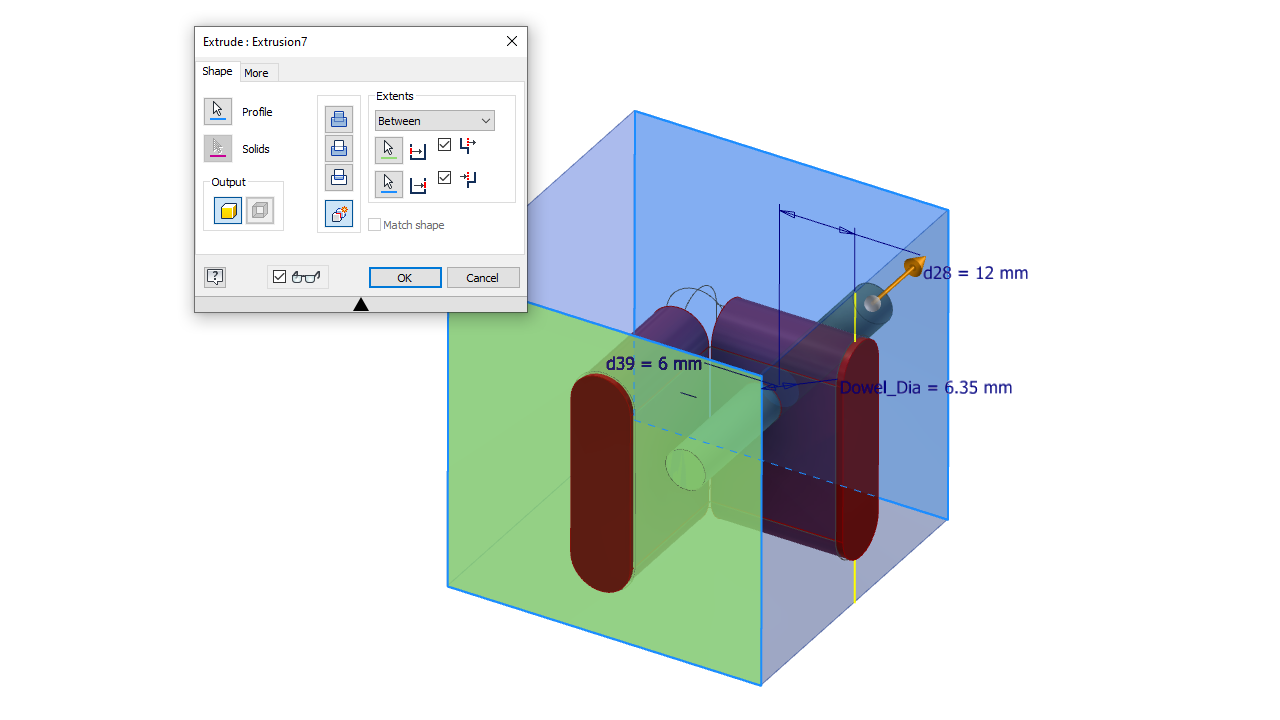
The first Dowel is created.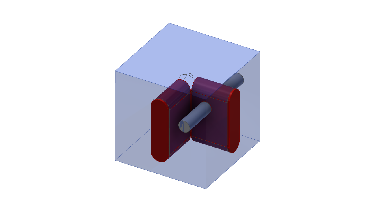
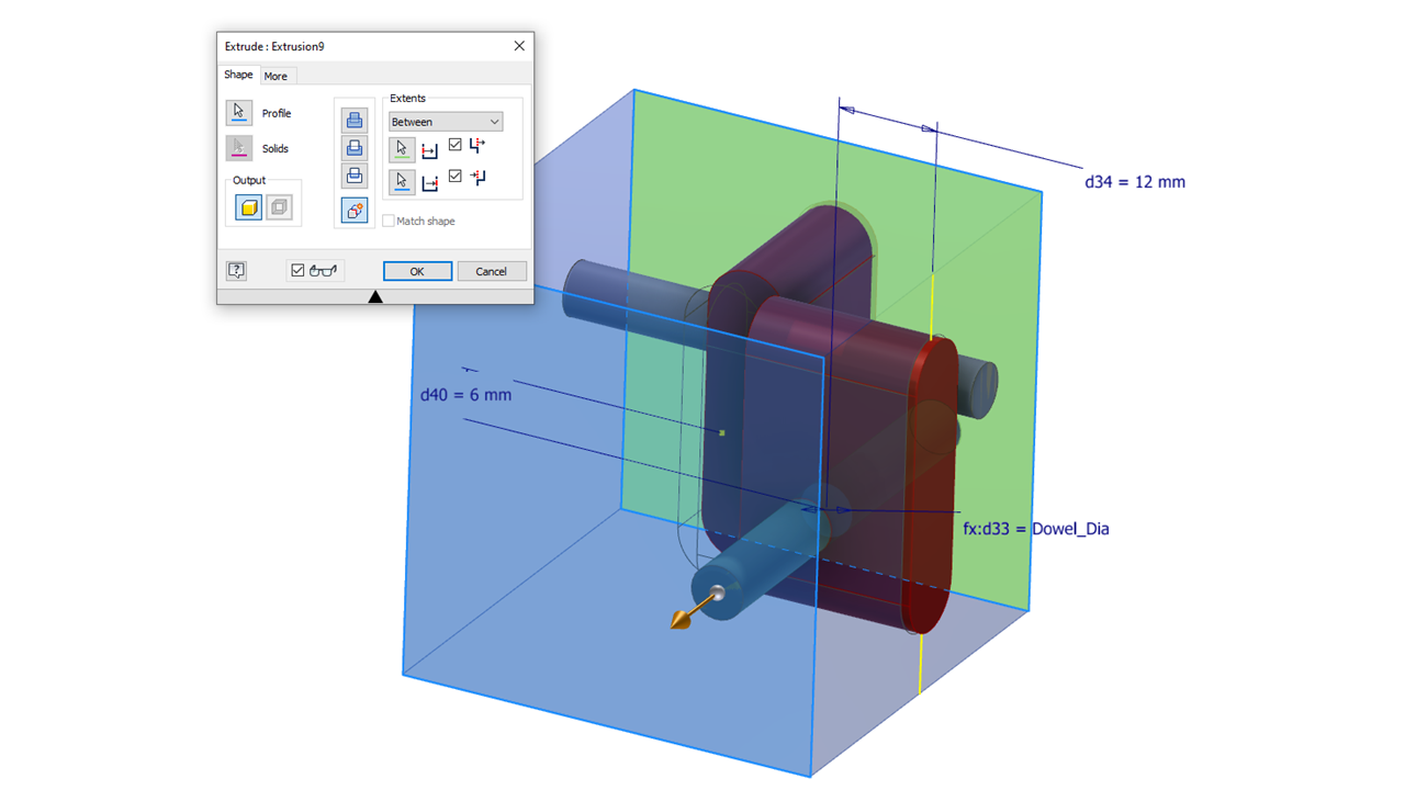
Step 12 – Repeat the dowel hole creation as per Steps 9 – 11 for the other joint.

Finally you will have a single corner Joint which can be placed in your assembly.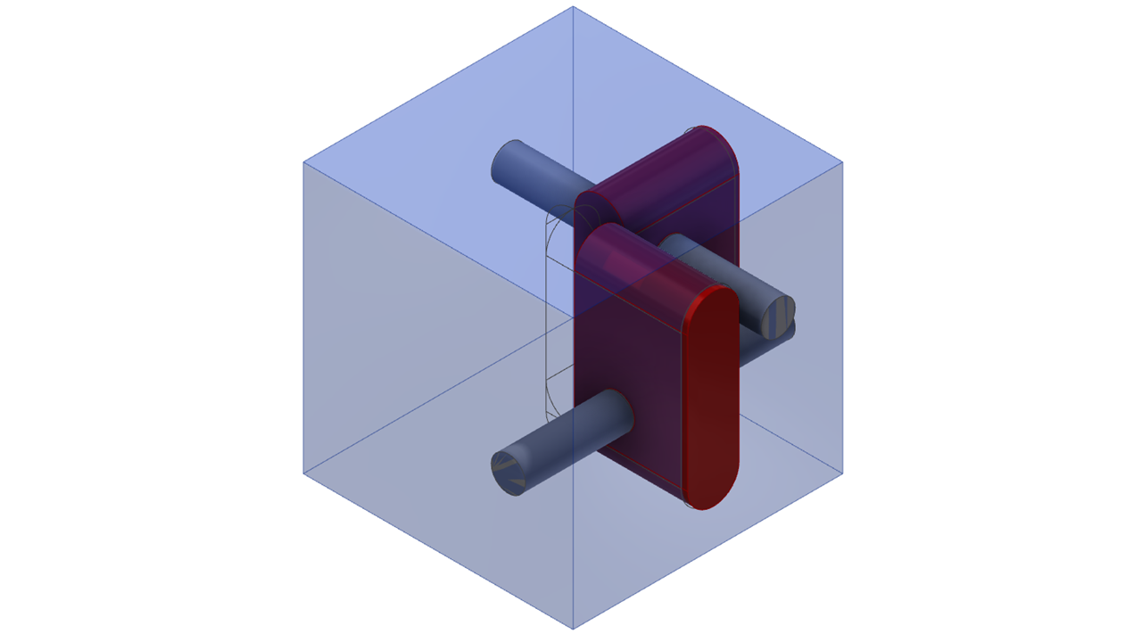
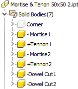
Finally you need to add the Woodwork for Inventor intelligence to allow the sculpt tool to work. Simply name your solid bodies.
+ = Add material
– = Subtract Material
You could assign iMates to pre-define how this will be assembled or you could setup the four corners and place within an assembly. I have uploaded a copy of the joints for download which will work with Inventor 2019 upwards.
Don’t forget to make your assembly Flexible before placing!

Happy Holidays from Living on the Edge Band and may you all have a great 2020.
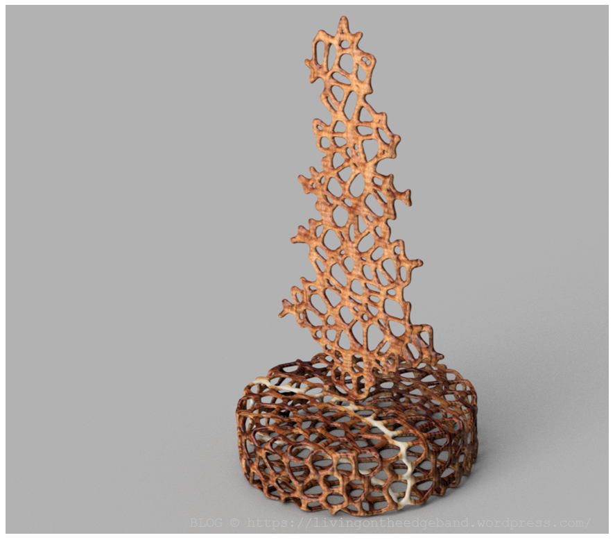
Voronoi Trees this year!!! Download the STL from my GrabCAD account. https://grabcad.com/library/xmas-tree-voronoi-1

At times you may want to save, open and even merge BOM information using the BOM specification tool. Normally this is accessed via the CAD interface but there is another way.
Locate the executable C:\Program Files\Woodwork for Inventor 2019 v10\Woodwork4Inventor.BOM.exe
Create a shortcut on your desktop.
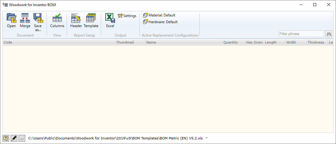
Once you run this app, you should see the BOM Specification dialogue appear as below.
It’s possible to create a snapshot view of your BOM using the save BOM function.

It will create a file with a .wbom extension which Can also be used to launch the BOM specification.
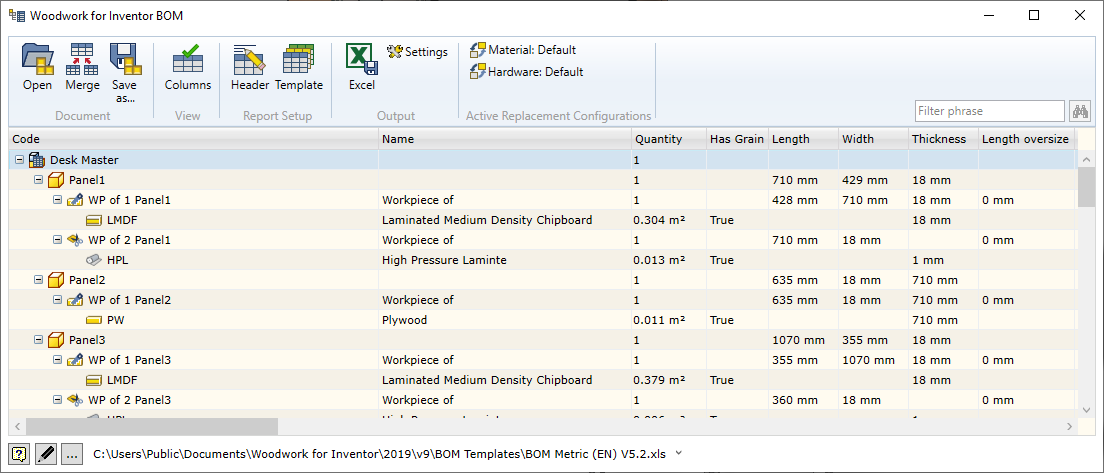
This will show an identical view of the BOM complete with the ability to export to Excel.

Well……. why not?
I’ve been using 3D CAD for more years than I can remember and keep “dipping my toe in the water” as it were, looking at what Fusion 360 has to offer alongside my trusty Autodesk Inventor modeller! Initially I was raving on this blog about taking Inventor models and rendering them with Fusion 360 because you could queue them up whilst they processed in the cloud, freeing me up to do other tasks and the quality seemed to have an edge over what Inventor could achieve.
Now there is a lot of noise about “Generative Design” at the moment and thought it’s worth a look to see what I could achieve with little knowledge and some instinct or “was that the “Learning Guide” appearing on the right of my session”?
Table Support
The Table support with a simple Aluminium cast base, with a wall thickness of around 10mm was a simple idea. A lot of these bases are usually ornate and cast in Aluminium, so I was interested to see what it could come up with.
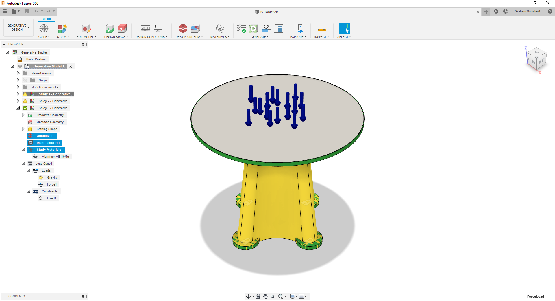
Define some Objectives such as minimise Mass or Stiffness, Safety Factor. Options for Additive, Milling or casting processes could be assessed.
Mark the bodies in your model you wish to Preserve (Green) to keep in your design Which won’t change such as the feet positions and table top. Next would be Obstacle (Red) geometry such as empty spaces. I didn’t actually specify any on this study. Then finally the Starting Shape (Yellow). This was really the main area of focus.
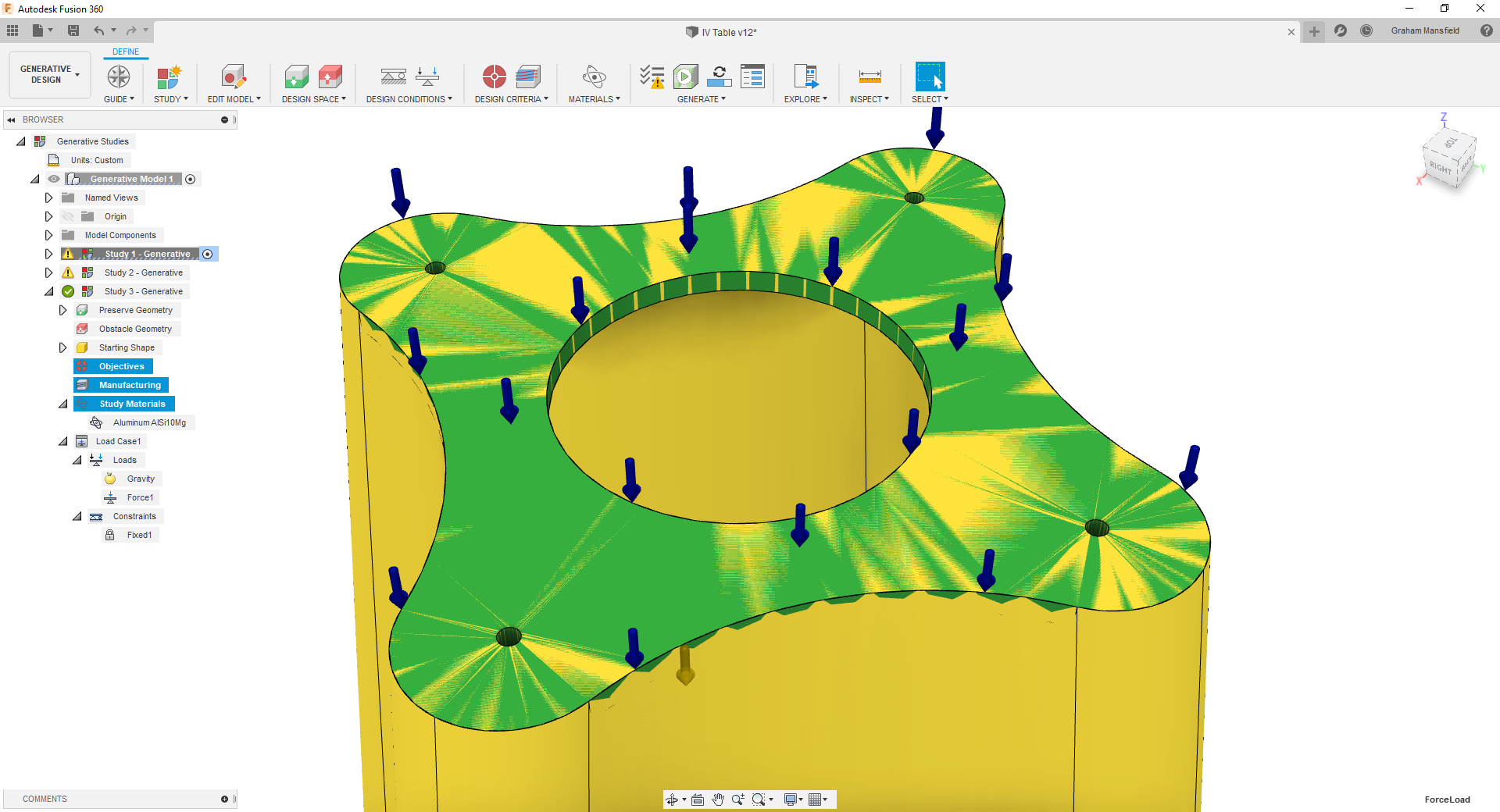
Chose your material if not already assigned and Load your design with a Force and Fix the feet so they don’t move. Then you can submit to generate a design and follow the generate status. This process takes a few hours to complete and the output called an outcome will be displayed.
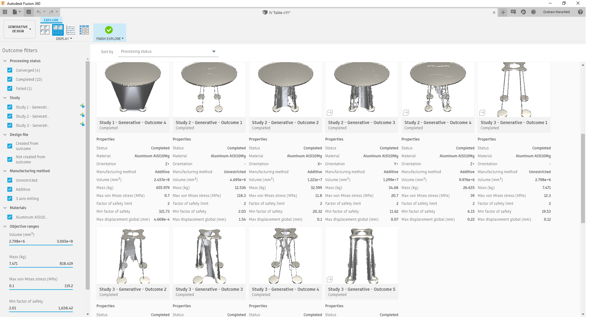
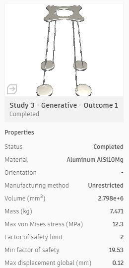
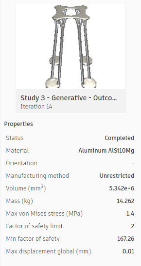
Each outcome will display Mass, von Mises stress and max displacement. The selected outcome can be previewed by rotating & zooming around the model tracking the different iterations at the base with a slider.
Lightest was only 7.5kg but a design that looked interesting was an acceptable 14kg once I machined the top and feet faces flat.
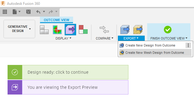
When happy that’s the design you want to work with, the finished results can be created into a new design within Fusion 360 but this will take a short time whilst it’s generated in the cloud.
In the industry I work in, I’m not sure how many times I would embark on using these tools, but for Aerospace, Automotive and Machinery Design there could be great designs that could be made. You will need some cloud credits to use this functionality, typically at the time of writing:-
Generate a study = 25 cloud credits
~100 outcomes, covers 14 Manufacturing types, 7 materials
Download an Outcome as Solid CAD for editable geometry = 100 cloud credits
Why not take advantage and give it a FREE try like I did? You currently get UNLIMITED try’s with Generative Design, until 31st December 2019!!
Enjoy!

Came across WRP Timber Mouldings Ltd trade supplier’s website www.wrp-timber-mouldings.co.uk the other day. It’s a great reference resource for CAD moulding profiles with lots of other interesting tips on the site and of course you can easily order the profile reference from the part number if needed.
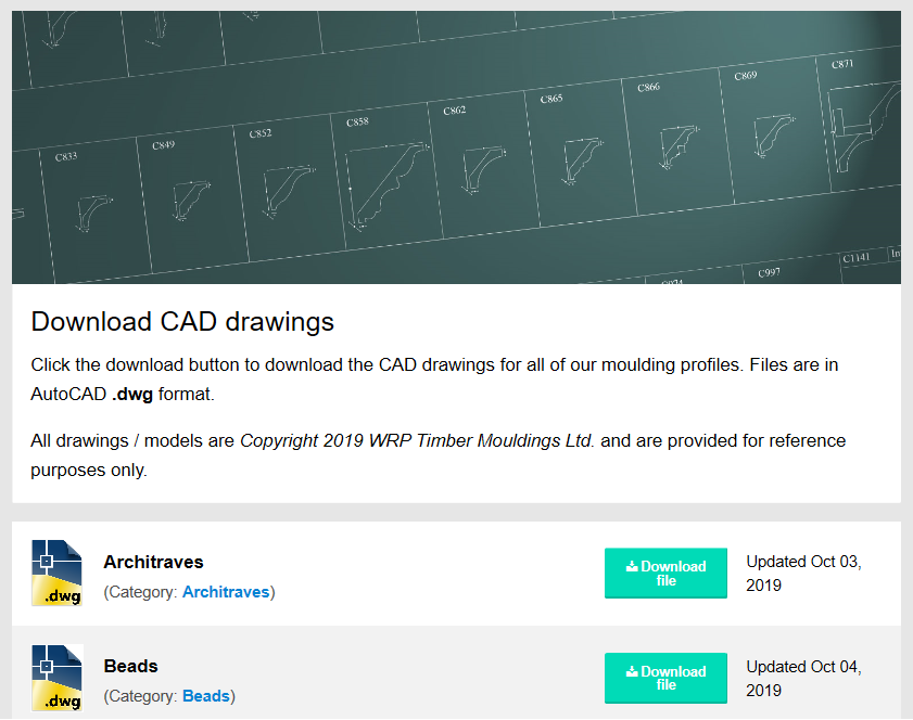 https://www.wrp-timber-mouldings.co.uk/download-cad-files
TIP When using with Inventor, don’t forget to make sure you use a sketchblock when placing in the sketch environment, it will be easier to rotate and position.
Disclaimer
I have no connection with WRP Timber Mouldings, products or services but thought it worth sharing!

Below is a useful list of Improvements and fixes added to the current release.
