What’s New Woodwork for Inventor v10

What’s New Woodwork for Inventor v10

It’s got a new logo but the devil is in the detail. This release excels by building on it’s foundations to deliver some impressive enhancements.

Enhanced Grain Direction Control

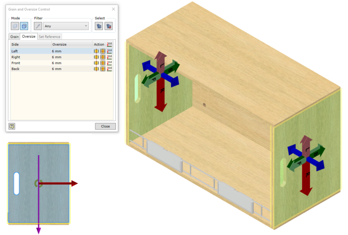
You can now Control grain direction on multiple panels. Adjust covers or material fills all in one go.

Before Rotated Grain

Rotated Grain

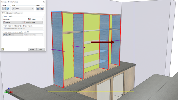
More control is achieved with the new layout dialogue.

Fill RotatedCovers Rotated

Over size Control Enhanced

Oversize5

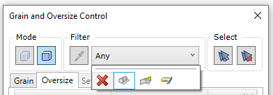
Multi panel or edge over sizing can be achieved working similar to the grain direction control.

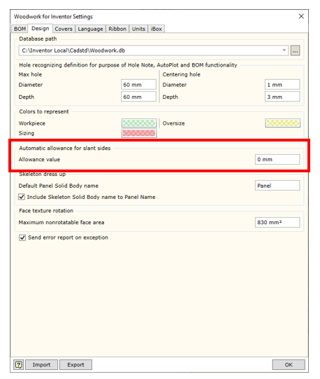
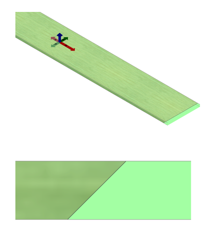
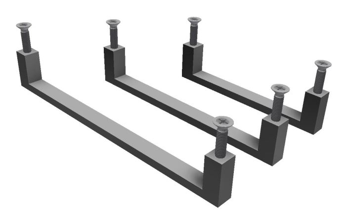
NEW Over size for Slant faces

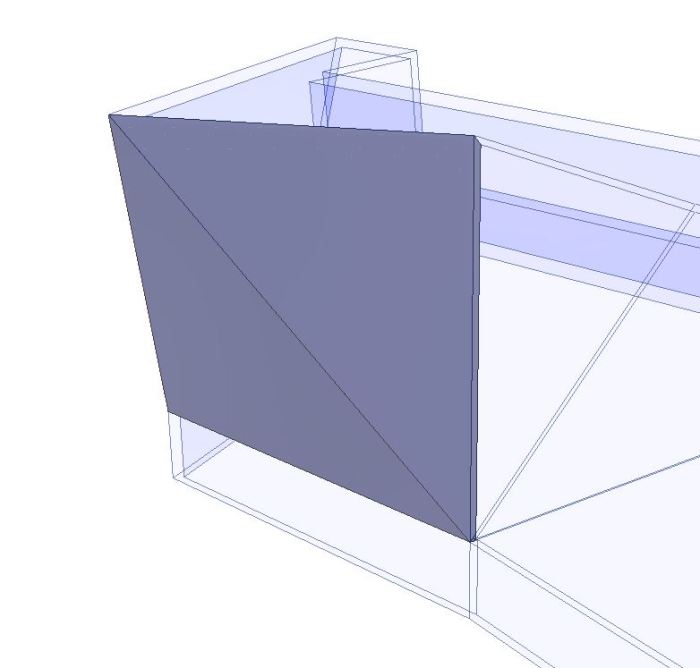
You can now set an allowance for over sizing  slant edges on a panel globally. Located under Woodwork for Inventor Settings > Design tab

Slant Ovesizing

Increasing by 20mm as the example shown below.

Slant Oversize set to 20mm

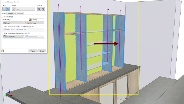
Enhanced Texture Direction Indicators

Enhanced indicators show panel orientation and grain direction.

New GD Indicators


Optimise Part Orientation for grain direction

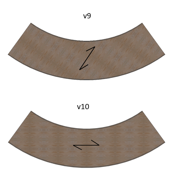
When applying a texture to a curved part in v9 it orientated along the x axis by default. You would then need to adjust the orientation to meet the longest edge requirement. Now  in v10 it will orientate the grain direction along the longest length of the bounding box which gives you more accurate BOM specification results.

Automatic longest length orientation for grain

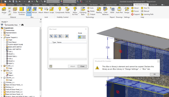
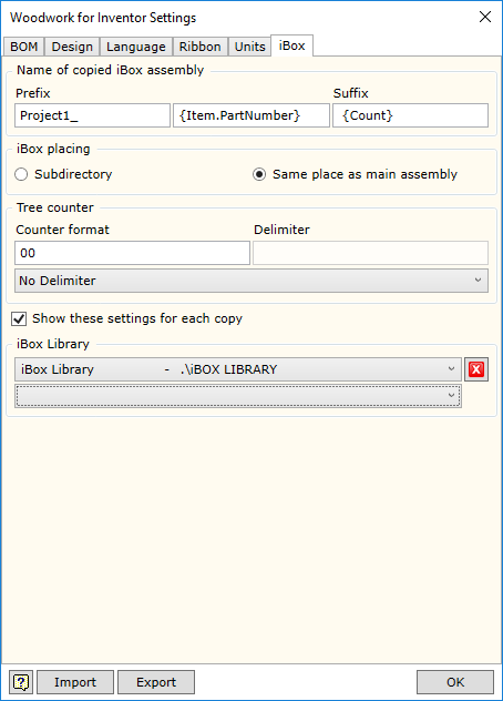
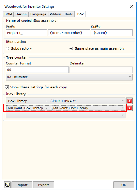
Enhanced iBox Copy design support

iBox now aligns with the Autodesk Vault Copy Design process with a unique identifier for it’s base component. When renaming your files this will not interfere with the iBox functionality.

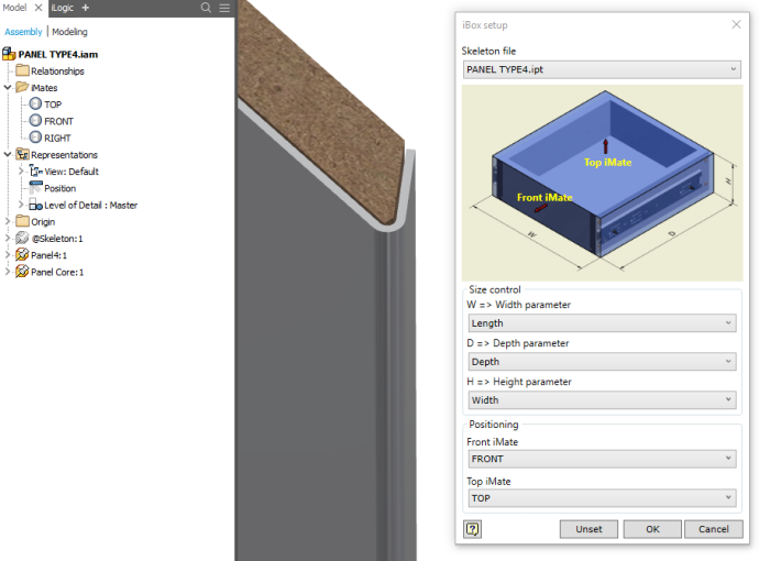
Auto-select base component

The skeleton file is now automatically selected when authoring an iBox. Note the new Unset button next to the OK button at the base of the dialogue box.

v10 iBox Enhancement

Enhanced Hardware Library

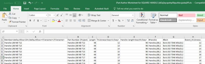
v10 iparts now support custom lengths as well as support for materialsv10 iPart support

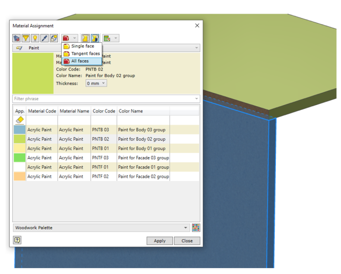
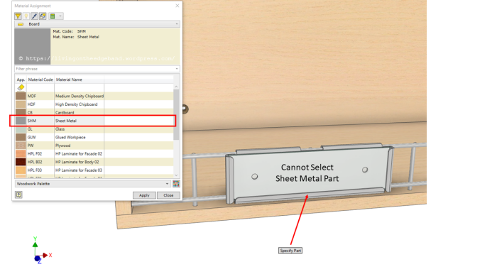
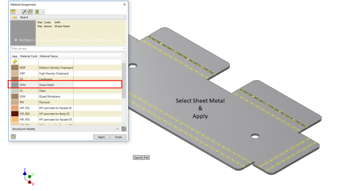
Enhanced Material Library

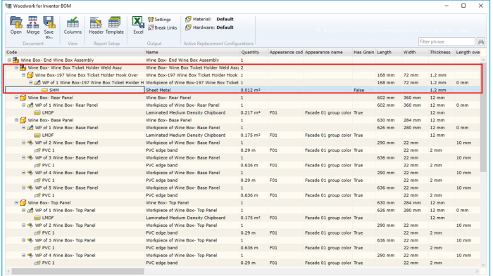
Painted panels are now reported in the BOM Specification as a single line item rather than every face as was previously available with v9. This is a much faster method when radius edges are used on panels or even when 6 edges are required. You can still use Single Face option if required.

v10 Paint all Faces

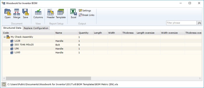
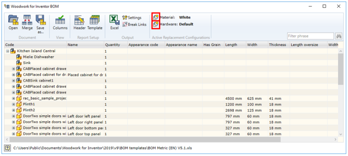
Extended BOM Specification Hierarchy 

New templates are provided to facilitate in passing data to ERP systems. these are found in C:\Users\Public\Documents\Woodwork for Inventor\2019\v10\BOM Templates.

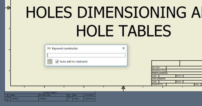
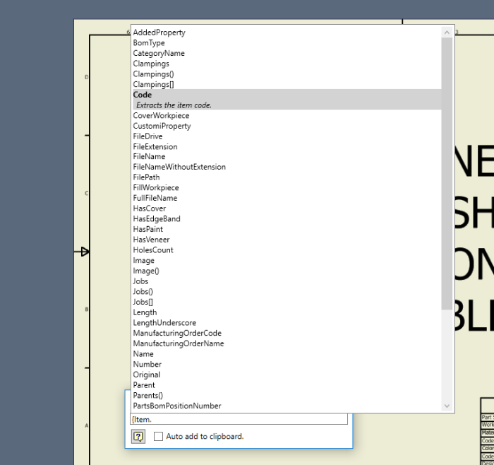
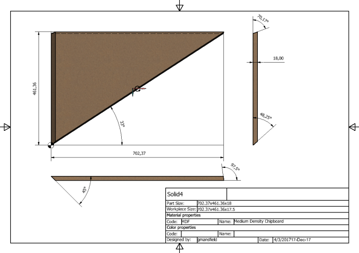
NEW Work-piece Angle Cut

Two new keywords have been made available for you to add these cuts to your BOM specification template. They are here for you to copy and paste into your template:

{item.FillWorkpiece.Left.CuttingAngle()}

{item.FillWorkpiece.Right.CuttingAngle()}

Accelerated BOM Specification Output

15-20x faster export to Excel. If there was one reason to upgrade to Woodwork for Inventor v10 it would be this alone. You will notice the difference. Nice job team!

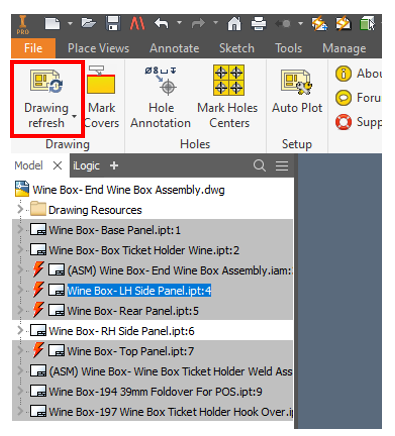
Enhanced Drawing Environment

Refresh content of a selected folder

Drawing Refresh Icon

Drawing Refresh by folder

Refresh only selected sheets option within Inventor’s Browser or via the Project dialogue. This speeds up the drawing update process when single sheets may contain large number of feature parts.

Drawing Refresh Selected Drawings by Browser

Drawing Refresh Selected Drawings

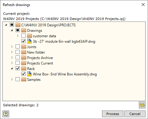
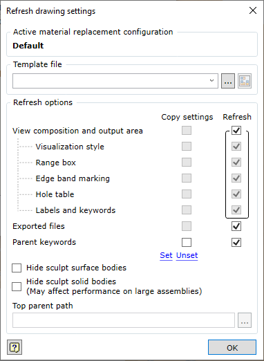
Access Drawing Settings when refreshing drawings.

Settings Button Drawing Refresh

Drawing Refresh Settings v10

New BOM Position number keyword – Latest link to all Keywords can be found here http://help.tools4inventor.com/doc/Keywords-for-Woodwork-for-Inventor-V10.pdf
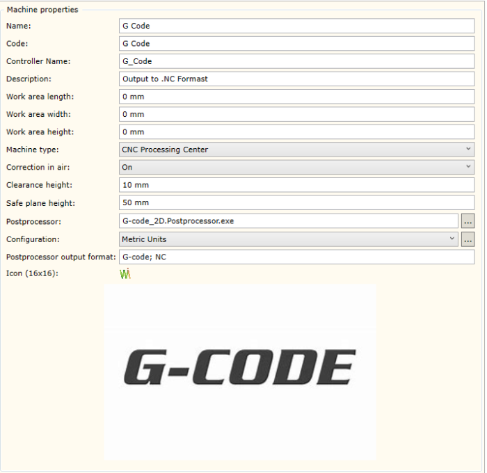
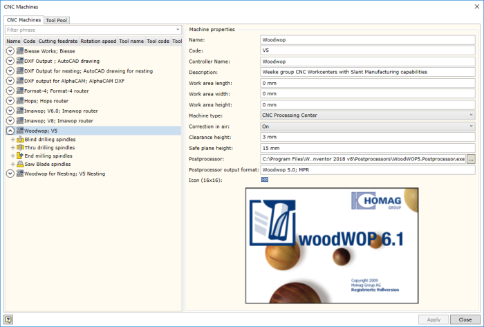
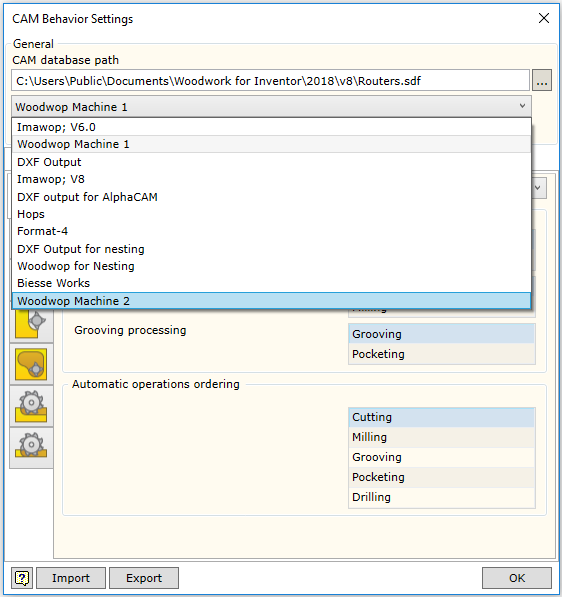
Enhanced CNC

Post Processor Support added for:

  • ShopBot 2D
  • Cobus NCAD xml

Enhanced SIZING operation can be applied automatically when assigning material. & over sized clamping options can be selected manually.

New Tooling Simulation Pre-Manufacturing Check

Simulation.png

Assembly Copier

Assembly Copier v10

The drawing name  now matches the component name when copying an assembly.

Naming Assembly Copier v10

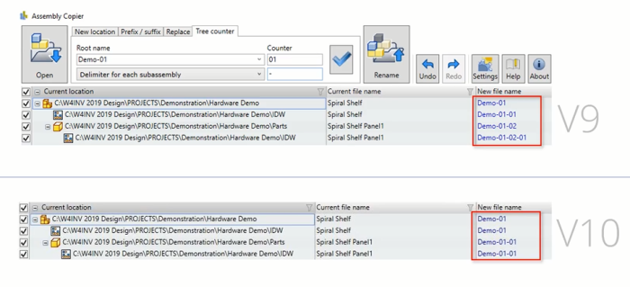
If you have a Level of Detail with suppressed components, they are now included in the copy.

Sheet Metal Parts Missing from Woodwork for Inventor BOM Specification?

Sheet Metal Parts Missing from Woodwork for Inventor BOM Specification?

Toolbar greyed out

You might wish to add metalwork alongside your joinery project and when you create the woodwork for Inventor BOM Specification nothing shows up. Also Woodwork for Inventor will not allow you to assign a material to a sheet metal part because the Woodwork for Inventor Ribbon is greyed out. In this short blog post I will show you what you need to do to make it work.

Cannot Select Sheet Metal Part Woodwork for Inventor

Woodwork for Inventor has Sheet Metal already included as a material type under the Board category. Simply edit your sheet metal part in context of the assembly and flat pattern it or open the sheet metal part file in it’s own window and you can assign the Sheet Metal Material.

Select Sheet Metal Part Woodwork for Inventor

Now when you run the BOM specification the Sheet Metal component will now display correctly with the right material and overall Length, Width & Thickness of the flat pattern.Sheet Metal material is shown in the W4I BOM

Enjoy.

Installing & Migrating to Woodwork for Inventor V9

Installing & Migrating to Woodwork for Inventor V9

If you are installing a shiny new copy of Inventor 2019 with Woodwork for Inventor for the first time then you do not need to follow these steps.

Already using Woodwork for Inventor then read on…

Woodwork for Inventor v9 now uses the JSON database platform instead of the Microsoft SQL Compact Edition and the developers have built in some migration tools to help automate the transition. There are various benefits for this change and I talk about them in my What’s new in Woodwork for Inventor v9 blog post.

As with any system upgrade, two things to consider here. Are you migrating to W4I v9 from W4I v8 on the same version of Inventor 2018? or are you jumping straight to Inventor 2019 with v9?  The following will give you some guidance but always make a backup of your data before doing anything.

Make a copy of C:\Users\Public\Documents\Woodwork for Inventor and your project CAD data files.

Installing W4I v9 from W4I v8 Inventor 2018 – Auto Migration

Download your Installation executable Woodwork_for_Inventor_v9.0_2018.exe from your account and obtain your new v9 serial number.

Run the installer with Admin Rights.

Install

Follow the prompts and W4I will auto migrate your settings.

old settings found

Finally your materials & and routers will be migrated into the new JSON platform database.

Migrate

Activate online by entering your new serial number. Each major release gets a new serial number. Enter your email and give your PC a name so that it can be identified should you wish to release the licence to transfer to another machine in the future. Simply submit your request.

Licence request

You can shutdown Inventor and restart  your licence should now be active.

Licence1

If it’s not yet active, and you try and request you will receive the following message.

Licence2

Installing W4I v9 with Inventor 2019 – Will be seen as a new Installation and will require Manual Migration.

Navigate to C:\Program Files\Woodwork for Inventor 2019 v9\DataMigrator.exe and run the Data Migrator tool. Map your previous installation settings, routers and materials. This folder could also be an earlier version, for example v7.

Manual Migration

Once migrated, you should be ready to go. Other files that may need to be copied to complete the process would be:

C:\Users\Public\Documents\Woodwork for Inventor\2018\W4INV Material Library.adsklib or your custom named library

to C:\Users\Public\Documents\Woodwork for Inventor\2019\W4INV Material Library.adsklib

You should now be able to start using Woodwork for Inventor v9.

What’s New Woodwork for Inventor v9

What’s New Woodwork for Inventor v9

This new version of Woodwork for Inventor v9 (available for Inventor 2017, 2018, & 2019) building on the foundation of v8, this release refines what is already a proven platform for anyone looking to improve their design to manufacture process.

It’s been just over two weeks since the launch of v9 (Officially 2nd May 2018, 13:00 GMT) and thought it was about time I’d share with you my thoughts on this new release.  V8 saw some real power functions added to the software. In this v9 release, it’s all about refinement and making a good product great!

The developers have focused on 10 key areas:

Summary of What’s New & Enhanced

  1. NEW – Material Replacement
  2. Enhanced – Edge Banding in BOM
  3. NEW – BOM Keywords
  4. NEW – Keyword Constructor
  5. Enhanced – CAM Module
  6. Enhanced – Pocketing Algorithm
  7. NEW – G-CODE Post Processor
  8. NEW– JSON Platform
  9. NEW – Databases Merged
  10. NEW –  Assembly Copier

1. Material Replacement

With previous versions we could access the replace material command from within the BOM Specification environment and replace the material codes and names.

v8 Replace Materials
Previous access to Replace Materials in V8

Now it sits alone in the ribbon as a standalone toolReplace Icon and can replace the material or material colour. Simply select via database or the materials in the current model.

Material Mapping
New Material & Colour Tool in v9
Options
Quickly configure material & colour options across an entire design

Watch an overview Video

Additionally, it can be used in Bill of Material (BOM) environment, as in the previous version. Simply select the material icon or if you wish to configure a different hardware setup choose the hardware icon.

Access from BOM v9 replace materials


The model is updated as well as the drawing bundle and any BOM specification generated.

2. Edge Banding in BOM

The user has much more options to specify the edge band legend (visualisation) in the BOM generated for the item. Now the user can request not only for the visualisation of the edge bands placed directly on the component’s edge that borders with the surrounding box, but also the edge bands that border with the edge of a surrounding box. The bordering type can also be generated: Coincident, Tangent, and Point. This makes it easier for the user to navigate the Bill of Material (BOM).

3. BOM Keywords

New keywords for Bill of Material (BOM) have been entered. It define the part’s shape and its coating. Now the user will be able to see whether the part is rectangular and if it contains holes, edge banding, etc. in Bill of Material (BOM) Specification.

4. Keyword Constructor

A new keyword prompter called Keyword constructor has been implemented.

Keyword Constructor

While editing the Excel BOM or drawing templates, the user has an option to use keyword constructor which allows for generating the necessary keyword eliminating syntax errors.

Keywork constructor List

These keyword strings can be copied to the clipboard and pasted into the location within the template. It reduces the time required to adjust template forms.

5. CAM Module

The automatic functioning of CAM module has been improved. Now different setting options can be configured for several CNC machines with one post-processor.

6. Pocketing Algorithm

The pocketing algorithm has been corrected in the CAM module. A correction has been made to the calculation when milling an open pocket edge.

7. G-code Post Processor

New G-Code post processor has been created. Although this post had a sneek preview in W4I v8 if you were looking in the right place.

G-Code

8. JSON Platform

The Woodwork for Inventor database has been migrated to the JSON platform.  Now the data service does not require the SQL compact driver.

Performance over a shared network and database locking for editing are just two great reasons this has been implemented. It’s fast….

Json

9. Databases Merged

Woodwork for Inventor materials, CNC machine database, and CAM behaviour settings are merged into a single database which helps facilitate certain interaction issues between Woodwork for Inventor materials and CNC machines. Also, it increases the overall operational reliability of the system.

10. Assembly Copier

Assembly Copier

The Assembly Copier function has been re-written for Woodwork for Inventor v9. Various linked files can be included in the list of copied items. Therefore, various MS Excel image-type linked files become items that can now be copied. This gives the user much more flexibility in adjusting the behaviour of the Assembly Copier.

Overall, we are now able to utilise the power of Inventor 2019 and this release seems to bark refinement & speed. Well done Woodwork for Inventor Team!

Managing Woodwork for Inventor CAM multiple configurations

Managing Woodwork for Inventor CAM multiple configurations

You have multiple machines that have different configurations of Tool libraries for different types of work in the factory. Here’s how you can create a copy of a base setup to modify later.

Enter the Woodwork for Inventor Machine Setup. Navigate to the machine you wish to duplicate. In this example it’s Woodwop ;V5

Std WoodWOP setting

RMB and Copy

Copy Machine

Rename the first machine Woodwop Machine 1 ;V5 and then rename the second machine Woodwop Machine 2 ;V5. You can now customise your Tool Pool with the appropriate tools for Machine 2

Copy Machine complete

You can toggle easily between machines either add-hoc when creating a nest or simply processing automatically.

Option available

Nesting – Setting Default Board Size

Nesting – Setting Default Board Size

Someone asked… “How to change the default board size when nesting panels”?

This process is pretty straightforward. Out of the box your nested board default size will be set to 2800mm x 2070mm. We need to make this 3050mm x 1220mm for the material MDF.

Default nest size 1

First things first, Woodwork for Inventor CAM will create a nest based on the Woodwork for Inventor material you have assigned to your model and will group together all panels that are the same material and thickness. You can map different sizes based on machine so this is pretty flexible.Assembly for Nest
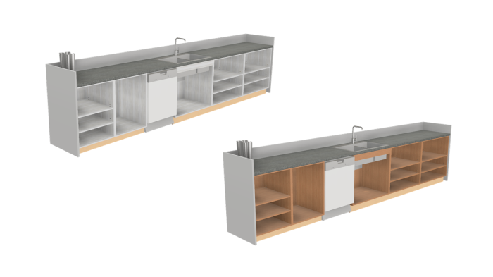
When creating a nest of an assembly the output may look like this for the 3 materials used in this assembly.

Sheet1 18mmSheet2 12mmSheet3 18mm

In this example we are just going to change the size for MDF material which is going to the CNC Machine, Nested Woodwop Output. Here all sheets are 2800mm x 2070mm.

Adding 3050x1220 to Woodwop Nest
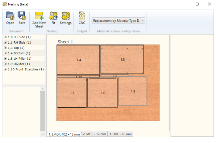
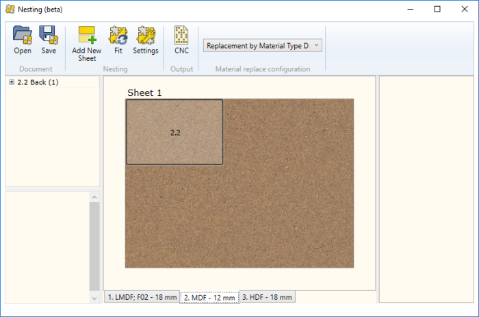
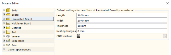
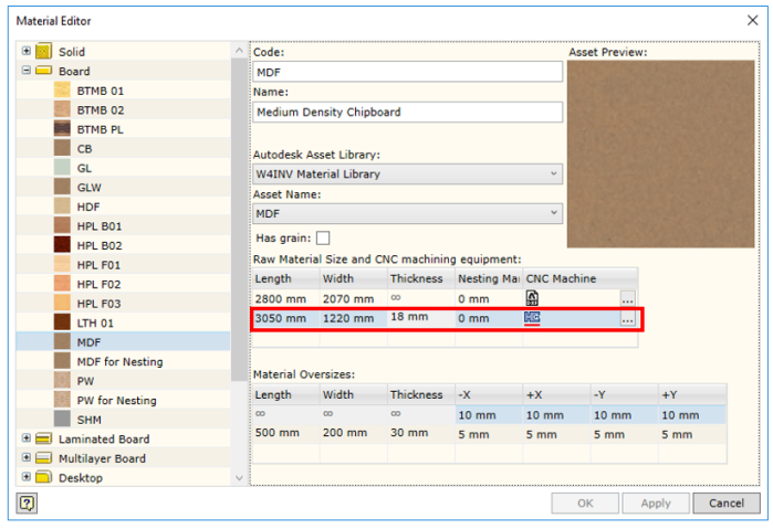
If you are adding custom materials you can setup the default under the Materials Editor and this will become the seed size for every material type you setup.

Sheet 2 Now 3050 x 1220


Happy Nesting!

Angled Reception Desk – Create Perfect Panel Detail Inventor Modelling Tip

Angled Reception Desk – Create Perfect Panel Detail Inventor Modelling Tip

 With any CAD system there is always a way to create what you need. It’s just the best way might not always be obvious. I’m hoping this Tip will help everyone who needs to create the perfect panel.

Let’s start with the basic reception desk shape. Our interest initially lies with the external shape. We can sketch, use tools such as “Split Face”, “Face Draft” and “Direct Edit” to achieve the result.

Desk1
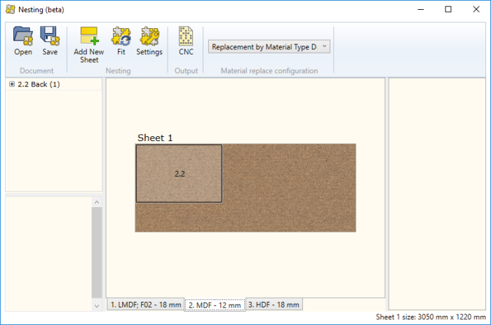
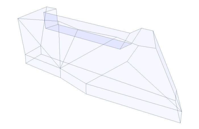
The next step is where we need to create the panel thickness as a uniform size or even override individual faces for this. Here, we can use the Shell tool.

Desk2

We are now ready to create our individual panels. We are going to use Inventor’s Loft tool and set to create individual solids each time.

Desk1aDesk1bDesk3

We simply select Edge 1 loop then Edge 2 loop and we will achieve a linear loft transition which maintains the edge condition used to scribe the panels together.

Desk4

Once completed we can simply use Inventor’s Make Components tool to generate a working assembly to place Woodwork for Inventor materials.

reception-desk-master1.png

When creating your drawings you can now obtain the angles you require to finish the job.Desk Panel Drawing example

iBox Library path setting

iBox Library path setting

After setting a new Library Path for your custom iBox templates, you get an error message. “This iBox is library element and cannot be copied. Declare this library as an iBox Library in “Design Settings” -> “iBox” tab.

Sometimes because you are using a Vaulted Project file this will be read only. If you are upgrading from a previous version of Woodwork for Inventor, normally all your setting will be migrated. However, if you do have a vaulted project you need to check it out of the vault to edit.

By default Woodwork for Inventor comes with a pre defined Library folder called iBox Library. If this is missing simply add your own or you may wish to add an additional library.

Setting Project

After adding your library path to your project, when you go to place one of your templates you will now see the error message:

“This iBox is library element and cannot be copied. Declare this library as an iBox Library in “Design Settings” -> “iBox” tab.

Error when placing iBox.PNG

To resolve this error. simply choose Design from the Settings ribbon.

Design Settings1

Now Add your new path. If you choose the drop down it will automatically show the created path. In my example I added Tea Point iBox Library.

Design Settings2

Now you can add your templates in the usual way.

Lock Specific Panels from Sculpt & Auto Plot

Lock Specific Panels from Sculpt & Auto Plot

On some occasions you would like to exclude certain panels from the Sculpt operation.

To enable simply select a panel in the Inventor browser, right click and enable “Lock from Sculpt” Lock from Sculpt

To remove the override for locking your panel from sculpt simply right click and “Unlock” Unlock from Sculpt

As you can see the same process can be applied to Lock or unlock panels from participating in the Auto Plot process.

Formatting Inventor iParts to show in Woodwork for Inventor BOM

Formatting Inventor iParts to show in Woodwork for Inventor BOM

In a previous blog post I described how easy it was to add parameters to a bought out part to show up in the Woodwork for Inventor BOM Specification. However, what happens when you wish to use an Inventor iPart because you want to have some variation on the same theme?

Handle variations
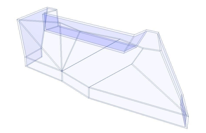
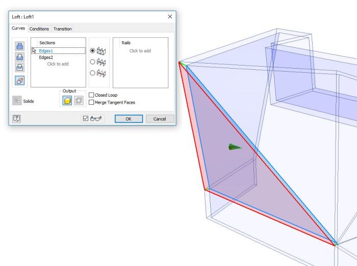
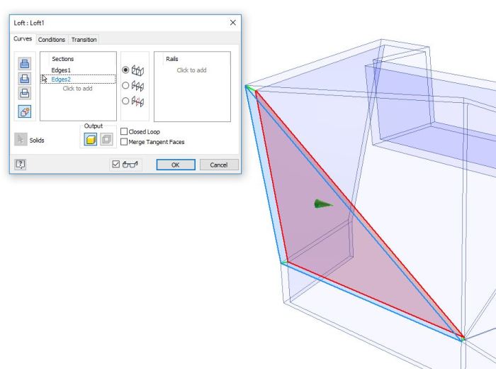
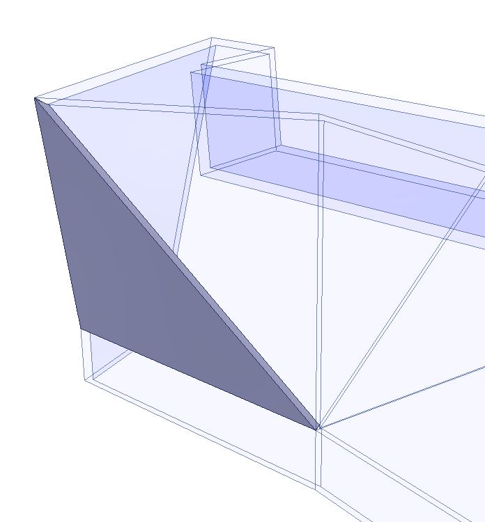
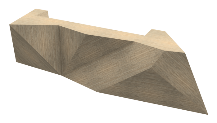
It’s pretty straight forward with just a few steps.

  1. Place the component name in a new column Header (best to add this via the MS Spreadsheet Editor) in this example we need to call it #HandleEditing iPart Factory in Spreadsheet
  2. Now we can describe the first variant line Handle;LO;1 where Handle is the Part Number, L96 is the Name and 1 is the qty.
  3. You can describe the Bolt in the same manner #Bolt for the Column header.
  4. Add Bolt;ISO 7046 M5x20;2 etc. and fill in the remainder of your table to suit your requirements.
  5. You now need to set your ipart to Phantom from selecting Tools>Document Settings>Bill of Materials> and change default BOM structure to Phantom.Edit Document Settings
  6. After placing your configured iPart in an assembly and running the BOM specification within Woodwork for Inventor you will see your components appear.BOM Specification Check